11.RS-232C INTERFACE(OPTION)
80
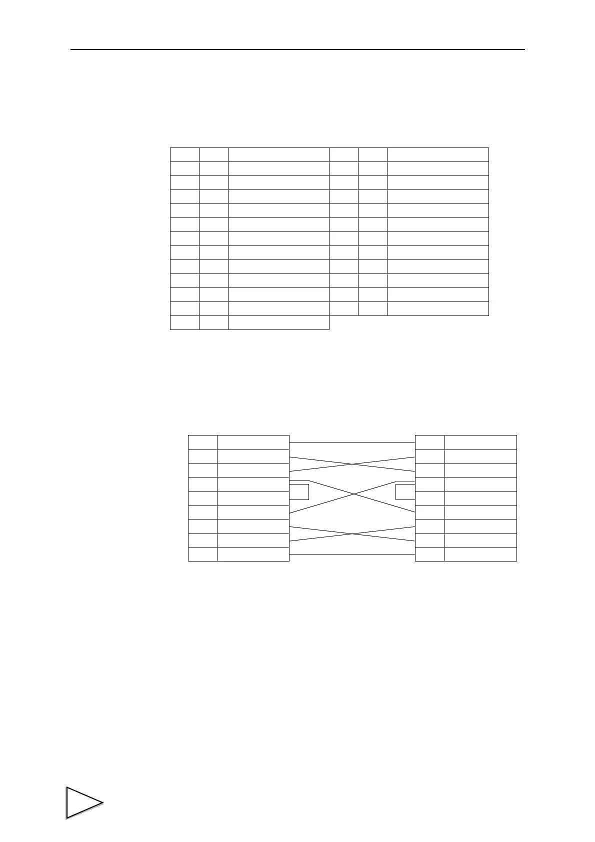
11-1-2. Connector Pin Assignment
11-1-3. Cable
* This connection diagram shows an example of connecting a DTE (data terminal
equipment) personal computer.
Use a straight cable for connecting a DCE (data circuit terminating equipment) such
as a modem.
* Before preparing a cable, check the connector shape and pin assignment of the
equipment to be connected again.
Adaptable plug: 25-pin D-sub connector(JAE make DB-25P-N etc)
1
*
FG 14
2 out TxD 15
3in RxD 16
4 out RTS 17
5in CTS 18
619
7
*
SG 20 out DTR
821
922
10 23
11 24
12 25
13
1
2
3
4
5
8
6
20
7
FG
TxD
RxD
RTS
CTS
(CD)
(DSR)
DTR
SG
1
2
3
4
5
8
6
20
7
FG
TxD
RxD
RTS
CTS
CD
DSR
DTR
SG
F370 PC etc・・・
Cross Cable