J
Jennifer SmithAug 6, 2025
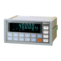
What to do if Unipulse F701+ show Gross over?
- NNicholas HamiltonAug 6, 2025
If your Unipulse Measuring Instruments display 'Gross over', reduce the input signal from the load cell until the over scale display disappears. Alternatively, change the gross over setting value. To prevent error displays, set the gross over setting value to the same value as the capacity.