37
4 Performing Final Discharge Control
37
Performing Final Discharge
Chapter
4
4-9. External I/O signal (control connector)
I/O circuits and internal circuits are electrically insulated by photo-coupler.
An external DC24V (power source for the external I/O signal circuit) must be prepared separately.
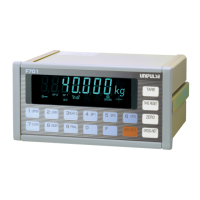
4-9-1.Connector pin assignments
Compatible connector: 57-30240 manufactured by DKK
* COM [1, 12, 13, 24 pin] is internally connected for sink type.
* COM [1, 13 pin] is internall
y connected as +24V and [12, 24 pin] as +24V_RTN respectively for
source type.
4-9-2.I/O selection setting
Perform the setting for I/O input signal.
No. Signal No. Signal
1 * COM (sink type)/+24V(source type) 13 * COM (sink type)/+24V(source type)
2 IN G/N 14 IN Input selection 1
3 IN D/Z 15 IN Input selection 2
4 IN One-touch tare subtraction 16 IN Input selection 3
5 IN Input selection 5 17 IN Input selection 4
6 OUT Near zero 18 OUT Lower limit
7 OUT SP1 19 OUT Upper limit
8 OUT SP2 20 OUT Stable
9 OUT SP3 21 OUT Output selection 1
10 OUT Under 22 OUT Output selection 2
11 OUT Over 23 OUT Output selection 3
12 *
COM (sink
type)/
+24V RTN (source type)
24 *
COM (sink type)/
+24V RTN (source type)
[Top view]
121110 9 8 7 6 5 4 3 2 1
242322212019181716151413
[Input selection] (Setting mode 5-1)
Input selection 1 *1
Input selection 2 *1
Input selection 3 *1
Input selection 4 *1
Input selection 5 *1
* 1
0: Hold/judging 1: Feeding/discharging
2: Start 3: Stop
4: Accumulation command 5: Accumulation clear
6: Total print 7: Erase printing
8: Pause 9: Tare reset
[Output selection] (Setting mode 5-2)
Output selection *2
* 2
0: Run 1: Paus.ed
2: Waiting for external judging input 3: Knocking
[Weighing function 2] (Setting mode 2-2)
1: Complete Output
0: Go output
Output selection (22 pin)
2: Weight error and seq. error
1: Seq. error
0: Weight error
Output selection (21 pin)