10
1 Before Getting Started
10
Before Getting Started
Chapter
1
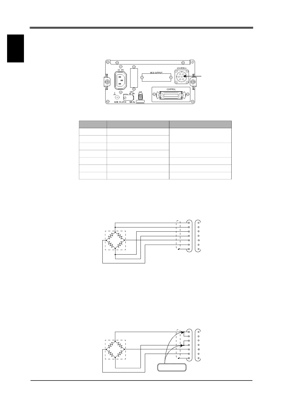
1-11. Load cell connection
The excitation voltage of the F701+ is 10V, the maximum current is 120mA, and up to four 350Ω load
cells can be connected in parallel.
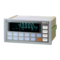
■Six-line type connection
The input terminal block of load cell of this device is six-line type (remote sensing type). Be sure to use
a six-core shield wire for connection with the load cell and perform separate wiring for lines with a lot
of noise (wiring for electrical power equipment, digital eq
uipment and so on) and AC lines.
A remote sensing type is used to stabilize excitation voltage value near load cell in order to prevent
excitation voltage to the load cell from fluctuating (cable resistance value from varying due to
temperature change).
■Four-line type connection
As outlined below, connect 1 with 2 and 3 with 4 respectively at the terminal block. Normal operation
appears possible if 2 and 3 of the terminal block are left open; however, high voltage is placed on the
load cell, which may cause heat and/or breakdown.
Connector pin assignments of load cell
Pin no. Signal (Six-line type) Signal (Four-line type)
1 +EXC
+EXC
(Connect No.1 and 2)
2 +S
3 -S
-EXC
(Connect No.3 and 4)
4 -EXC
5 +SIG +SIG
6 -SIG -SIG
7 SHIELD SHIELD
Load cell connector
+IN
-OUT
-IN
Load cell
+EXC
+S
-S
-EXC
+SIG
-SIG
SHIELD
+OUT
1
2
3
4
5
6
7
+IN
-OUT
-IN
Load cell
+EXC
+S
-S
-EXC
+SIG
-SIG
SHIELD
+OUT
1
2
3
4
5
6
7
Connect here.