39
4 Performing Final Discharge Control
39
Performing Final Discharge
Chapter
4
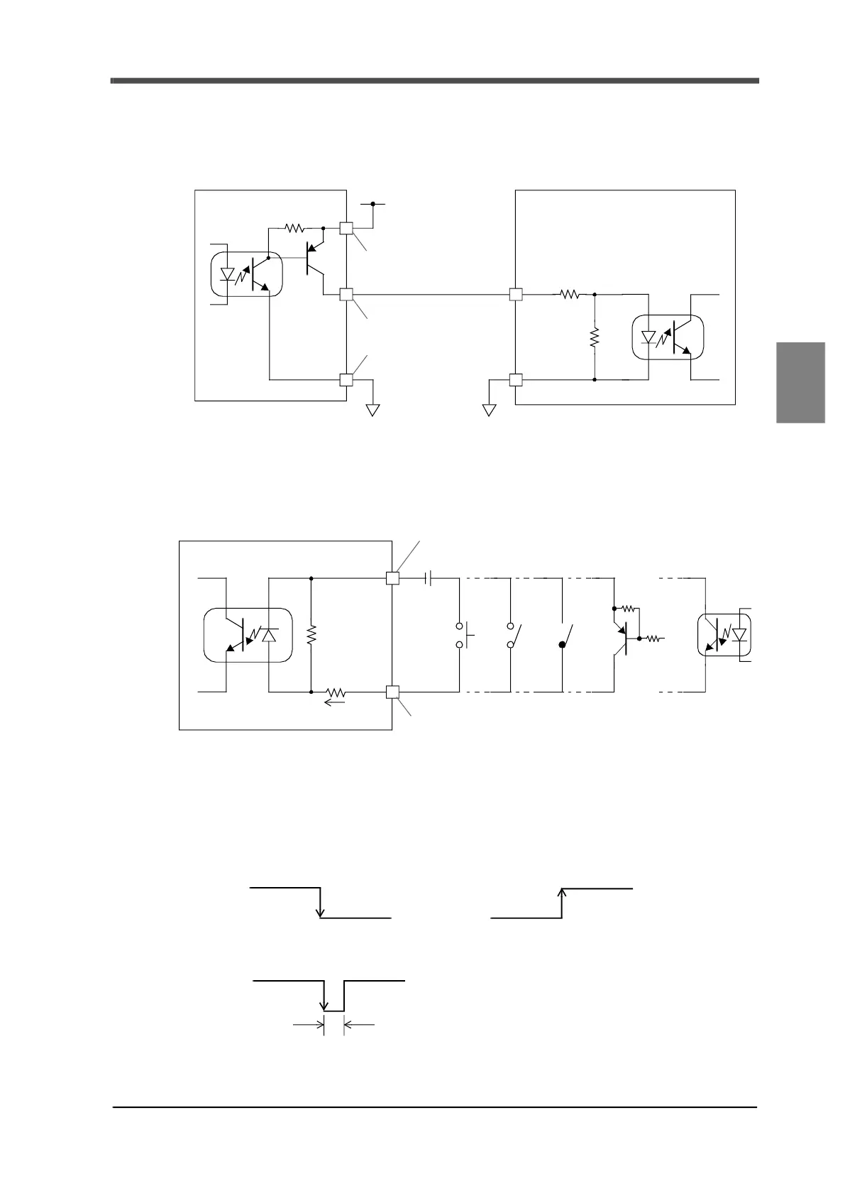
<Equivalent circuit and connection example for when source type is specified>
- Output
The signal output circuit is a photo-coupler insulated output (current source type).
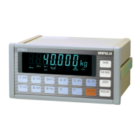
- Input
The device can be connected to switches, relays, transistors, photo-couplers etc.
A source type unit must be connected when connecting transistors, photo-couplers etc.
4-9-4.External input signal
There are edge input and level input for external input.
<Edge input>
Switch processes at ON edge (OFF→ON) or OFF edge (ON→OFF) of external input.
When processing at ON edge (OFF→ON).
Output
Input
COM
F701+
Source type
PLC etc.
+24VRTN
+24V
+24VRTN
[No.1, 13]
[No.6 to 11, 18 to 23]
[No.12, 24]
F701+
DC24V
Push Toggle
switch switch
Relay
contact
Input
Transistor
Photo-coupler
Input
COM
Ic=approx. 11mA
[No.12, 24]
[No.2 to 5, 14 to 17]
OFF
ON
OFF
ON
OFF
ON
Pulse range of 50msec or more