73
6 Useful Functions
73
Useful Functions
Chapter
6
6-11. Using an RS-485 interface (option)
RS-485 is an interface to read the indicated values and status of the F701+ and to write the setting
values into the F701+. This interface is convenient for processing such as controls, totals, and records
by connecting the F701+ to a PLC, programmable display unit and so forth.
6-11-1.Communication specifications
■ Standards
Message format Modbus-RTU/UNI-Format
Signal level RS-485 compliant, 2-wire
Transmitting distance Approx. 1 km
Transmitting method Asynchronous, half duplex
Transmitting speed 4800/9600/19200/38400/57600/115.2kbps
Number of connectible units Maximum 32 (including 1 master unit)
Bit configuration Start bit 1 bit
Character length Select from 7 or 8 bits (8 bits for Modbus-RTU)
Stop bit Select from 1 or 2 bits
Parity bit Select from none, odd or even
Terminator Select from CR, CR-LF
Communication mode Hand shake/Modbus-RTU
Selection code Binary (Modbus-RTU)/ASCII (UNI-Format)
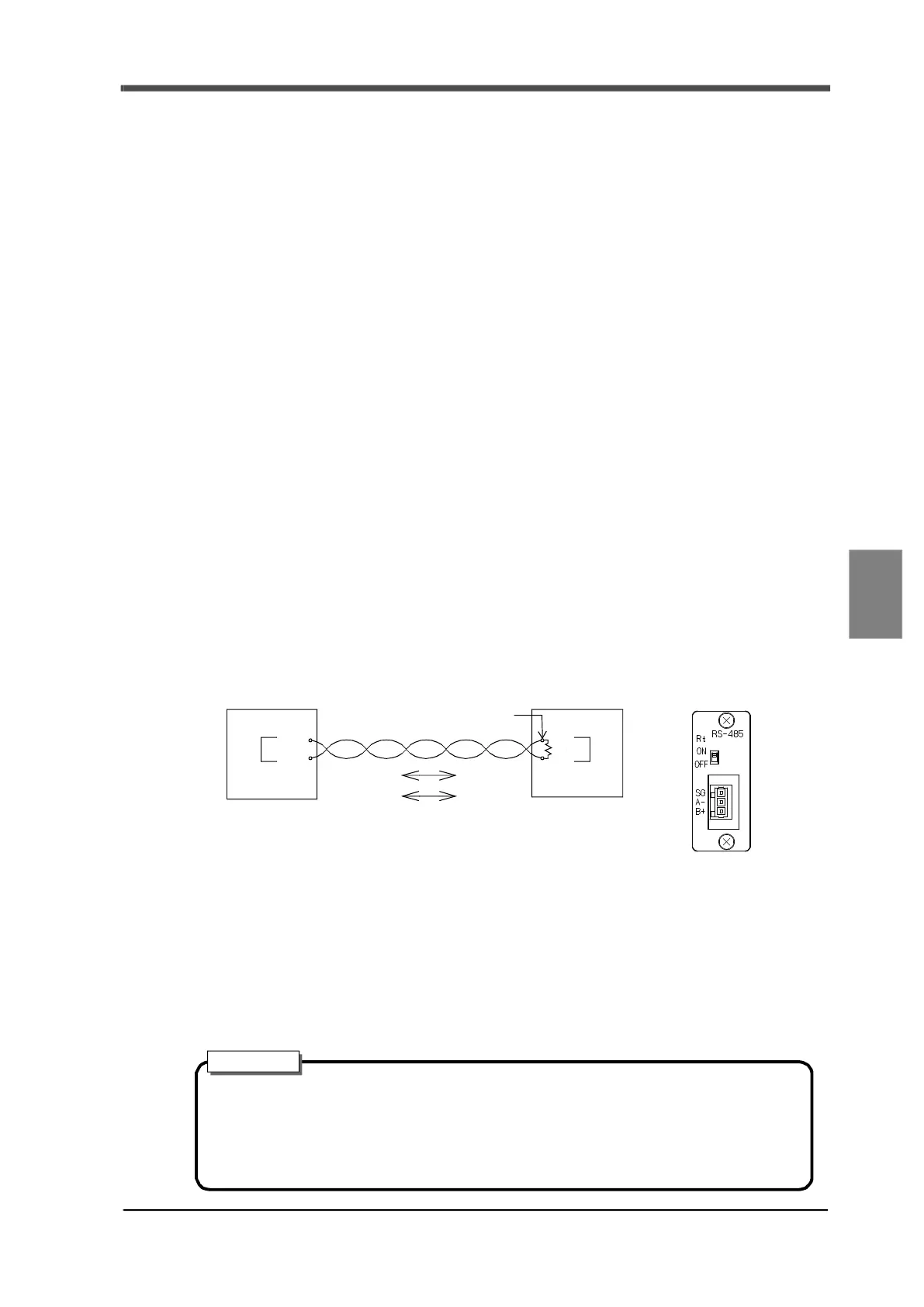
6-11-2.RS-485 connection
■ Two-wire (point to point)
- Use twisted pair wires for connection cables. (Noise margin increases.) However, two-core parallel
cables are sufficient for short-distance connection.
- SG terminal is a ground terminal (which protects circuits) used on the circ
uit. SG terminal does not
normally need to be used if the main unit of the F701+ and connection counterpart device are class D
grounded.
However, if connection is necessary based on the on-site conditions, check the specifications of the
counterpart device before connecting.
A
B
A
B
A
B
A*
B
F701+
PLC,
host computer and so on
Terminator
(Master) (Slave)
RS-485
- Mark status (OFF)
V
A-
V
B
< -0.2V
- Space status (ON)
V
A-
V
B
> 0.2V
(V
A
A terminal voltage)
(V
B
B terminal voltage)
- Depending on the master device, A and B may be indicated in reverse. If commu-
nication is not possible, switch A and B.
- Attach terminators on both the host and the F701+ sides.
- On the F701+ side, the switch should be on the upper side.
Attention