62
6 Useful Functions
62
Useful Functions
Chapter
6
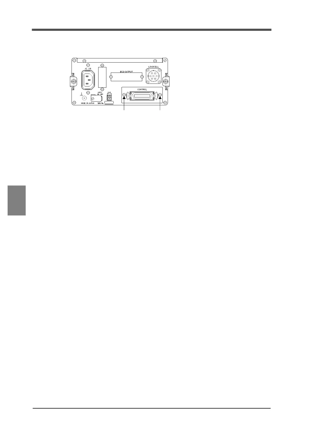
6-8. Replacing the I/O substrate
The I/O substrate can be replaced.
To replace the I/O substrate, remove the two M3 screws (1), pull out the whole control panel, and then
replace. After replacement, retighten the M3 screws (1).
(1) M3 screw (1) M3 screw