105
6 Useful Functions
105
Useful Functions
Chapter
6
6-14. Using the PROFIBUS interface (option)
F701+ PROFIBUS I/F is explained below. Basic knowledge for PLC and PROFIBUS is required to
read it. Refer to specialized materials for basic knowledge on PROFIBUS.
6-14-1.Specifications
- F701+ equipped with PROFIBUS interface can be connected as a slave device for PROFIBUS field
bus. (supports PROFIBUS-DP V0).
- Communication speed Supports 9.6kbps to 12M
bps (follows the master automatically)
(However, 45.45kbps is not supported)
- Occupying memory OUT 12 bytes (6 words)
IN 26 bytes (13 words)
(When assigning the address, ensure that the address is not
the same as other slaves.)
- Station no. The station address can be set from between 0 and 125.
- GSD file name UNIP0F61.GSDIN 26 bytes (13 words)
- Supports Sync Mode and Freeze Mode.
- Does not support Special Cl
ear Mode (Fail Safe Mode).
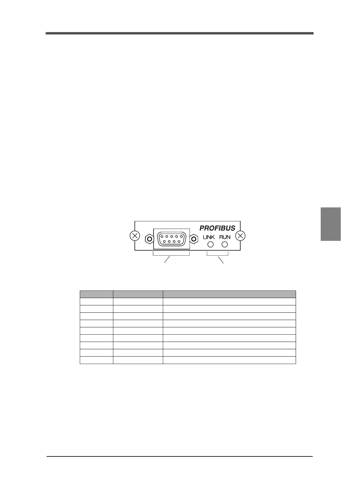
6-14-2.Details for each section
1. Connector for communication
* Prepare a connector of 9-pin D-SUB connector plug type for connection.
* Use PROFIBUS certified items for connector and cables. Ask the PROFIBUS Organization
about PROFIBUS certified items.
(Straight type, equivalent to 2744380 manufactured by Phoenix Contact.)
* Be sure to connect a terminator when the F701+ is at t
he end. Refer to specialized documents for
the procedure to connect a terminator.
2. Status LED
- LINK: Lights up while linking to the master device.
- RUN: Lights up when normal.
Pin no. Signal Function
1 (Unused)
2 - (Unused)
3 RxD/TxD-P Data reception/transmitted data Plus
4 CNTR-P Control signal (RTS)
5 DGND Data ground (0V)
6 VP Power supply for communication (5V)
7 (Unused)
8 RxD/TxD-N Data reception/transmitted data Minus
9 - (Unused)
1. Communication connector
Connector for connecting to PROFIBUS.
2. Status LED
Indicates communication status.