57
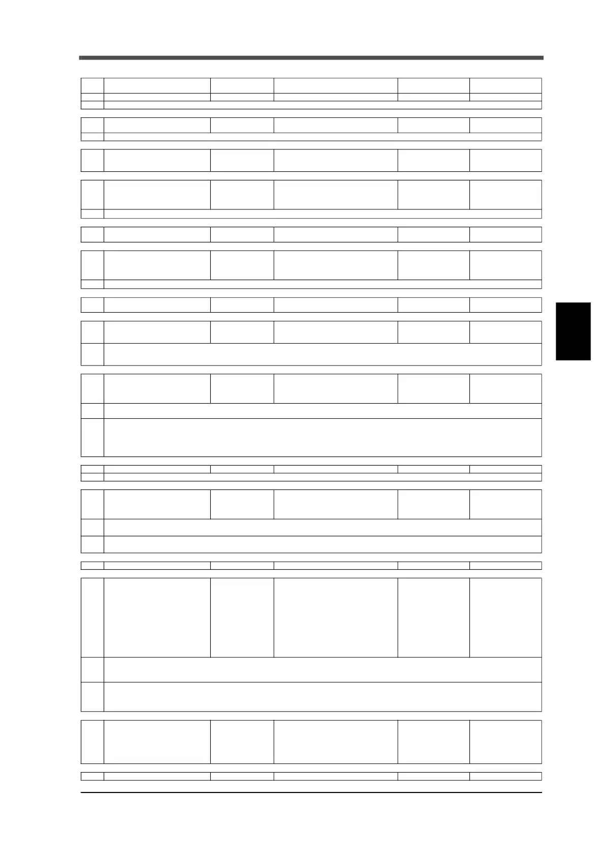
5 Timing Chart for Weighing
57
Timing Chart for Weighing
Chapter
5
↓
↓
↓
↓
↓
↓
↓
↓
↓
↓
↓
↓
↓
↓
No. Sequence control operation
Checking status
display
Keys for relevant settings
External input signal
to be used
External output
signal to be used
1 Waiting for start signal input
SP1/SP2/SP3 blinks
SP1/SP2/SP3 blinks at medium speed
2 Execution of tare subtraction Tare lights up
Setting mode 2-1:
final and over/under comparison
Tare subtraction
(5 pin)
Sets the compared weight value to z
ero (In the chart, tare subtraction is executed by external input and the NET weight is set to zero.)
3 Start signal ON is input
SP1/SP2/SP3
lights up
Setting mode 5-1: input selection Start (input selection)
Set point 1 (7 pin) ON
Set point 2 (8 pin) ON
Set point 3 (9 pin) ON
4 OFF condition for set point 1 SP1 light goes out
Setting mode 0-4: set point 1
Setting mode 0-9: final
Setting mode 2-1:
final and ove
r/under comparison
Set point 1 (7 pin)
OFF
* 1
Set point 1 output is OFF when compared weight value ≧ final setting value - set point 1 setting value
5
Operation of the comparison
inhibit timer
Setting mode 1-1:
comparison inhibit time (t0)
Set point 2 (8 pin)
OFF
6 OFF condition for set point 2 SP2 light goes out
Setting mode 0-5: set point 2
Setting mode 0-9: final
Setting mode 2-1:
final and over/under comp
arison
Set point 2 (8 pin)
OFF
* 2
Set point 2 output is OFF when compared weight value ≧ final setting value - set point 2 setting value
7
Operation of the comparison
inhibit timer
Setting mode 1-8:
comparison inhibit time (t1)
8
Input of pause signal ON and
waiting for restart
SP1/SP2/SP3
blinks
Setting mode 5-1: input selection
Setting mode 5-2: output selection
Pause
(input selection)
Set point 3 (9 pin) O
FF
Output selection:
paused (23 pin) ON
* 3
When the pause signal ON is input, status switches to paused, paused status output turns ON, and set point 1/set point 2/set point 3 turns
OFF.
SP1/SP2/SP3 blinks at low speed
9
Input of start signal ON and con-
trol status after restarting
SP3 lights up
Setting mode 5-1: input selection
Setting mode 5-2: output selection
Setting mode 5-5:
restart setting set poin
t 3
Start (input selection)
Set point 3 (9 pin) ON
Output selection:
paused (23 pin) OFF
* 4
During paused status, the operation is restarted when start signal ON is input.
When restarting, returns to the last control output status, after confirming stability.
* 5
The following restrictions apply to each of the control output statuses when restarting
- Restarting does not take place when the previous set
point 3 was in OFF status (because either the weighing has already completed or
weighing has not yet started)
- Set point 3 output turns ON in the following condition, weight value at restart > (final - compensation )× restart setting set point 3 when
set point 3 is ON.
10
Operation of the adjust feeding timer
SP3 lights up
Setting mode 1-4: adjust feeding time (t4)
Set point 3 (9 pin) ON
* 6 Set point 3 signal is ON for the duration of compensation feeding time
.
11 Judgment of set point 3 control
Setting mode 0-6: compensation
Setting mode 0-9: final
Setting mode 2-1:
final and over/under comparison
* 7
Switches to [No.10] sequence when compared weight < final setting value - compensation setting value
Switches to [No.12] sequence when compared weight ≧ final setting value - compensation setting value
* 8
Set point 3 output is OFF when compared weight value ≧ fin
al setting value - compensation setting value
(Set point 3 control in the chart due to the condition of set point 3 of restart setting)
12 Operation of the judging timer SP3 light goes out Setting mode 1-2: judging time (t2)
Set point 3 (9 pin) OFF
13
Output of complete signal and
output of judging signal
HOLD lights up
HI, GO or LO lights
up
Setting mode 0-7: over
Setting mode 0-8: under
Setting mode 0-9: fin
al
Setting mode 1-3:
complete output time (t3)
Setting mode 2-1:
final and over/under comparison
Setting mode 2-2:
output selection (22 pin)
Setting mode 2-2:
complete signal output mode
Over (10 pin) ON
Under (11 pin) ON
Output selection: GO
(22 pin) ON
Output selection:
complete (22 pin) ON
* 9
Under is ON when compared weight value < final setting value - under setting value
Over is ON when compared weigh
t value > final setting value + over setting value
GO is ON when final setting value + over setting value ≧ compared weight value ≧ final setting value - under setting value
* 10
The timing of complete signal output depends on setting mode 2-2: complete signal output mode (shown in the chart as 1: after judging
timer elapse)
The timing of over/under comparison holds the weight value compared at comple
te ON regardless of setting mode 2-2:over/under compar-
ison mode
14
After complete output timer has
elapsed
HOLD light goes
out
HI, GO or LO light
goes out
Setting mode 1-3:
complete output time (t3)
Setting mode 2-2:
output selection (22 pin)
Over (10 pin) OFF
Under (11 pin) OFF
Output selection: GO
(22 pin) OFF
Output selection:
complete (22 pin) OFF
......