9
Chapter 2: Mounting
The controller can be either panel-mounted or snap-mounted to a DIN rail.
Before You Begin
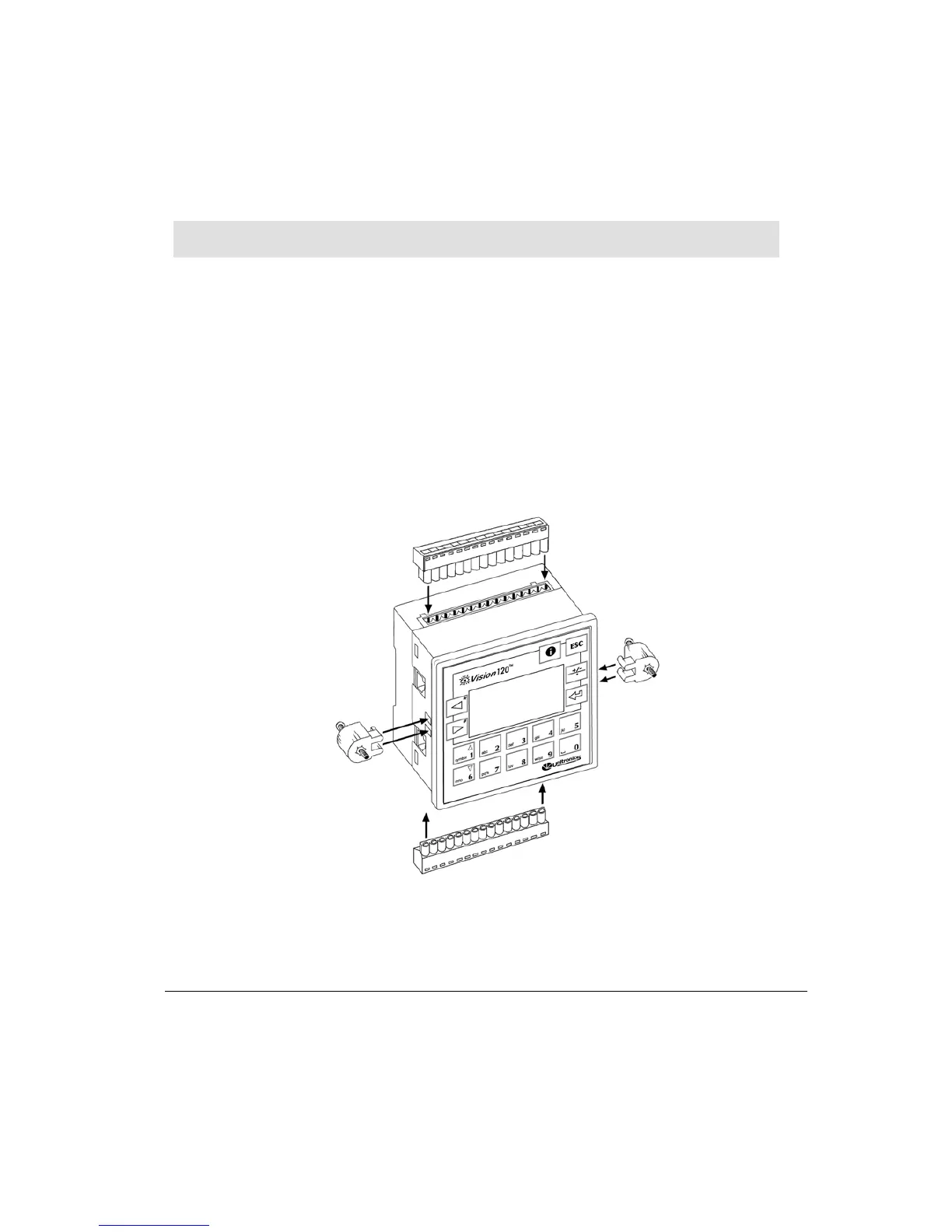
Before you begin installation procedures, check the contents of the controller kit. Standard
kits contain the controller, green plastic plug-in connectors, and 2 black plastic mounting
brackets, each with a screw inserted for panel mounting. These elements are illustrated in
Figure 2. The kit also contains a black seal, used for panel-mounting the controller; a CD-
ROM containing VisiLogic software, used to program the controller, a technical specification
sheet, and a programming communication cable. Kits comprising CANbus-ready models
also contain a green plastic CANbus plug-in connector. These items are not pictured in
Figure 2.
Figure 2. Connectors and Mounting Brackets