39
Figures and Tables
Figures
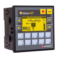
Figure 1. The Vision120 OPLC™ System ................................................................ 5
Figure 2. Connectors and Mounting Brackets ........................................................... 9
Figure 3. Panel Mounting the Controller ................................................................. 11
Figure 4. Panel Mounted.......................................................................................... 11
Figure 5. Snapping the Controller on to the DIN Rail............................................. 12
Figure 6. Proper DIN Rail Position.......................................................................... 12
Figure 7. Power Supply Wiring ............................................................................... 14
Figure 8. Increase the Contact Life Span................................................................. 17
Figure 9. Integrating I/O Expansion Modules ......................................................... 18
Figure 10. Connecting the PC to the Controller....................................................... 20
Figure 11. Opening the Controller ........................................................................... 23
Figure 12. Removing the Top PCB board................................................................ 23
Figure 13. RS232/RS485 Jumpers, Factory Default Settings.................................. 24
Figure 14. Replacing the Board ............................................................................... 24
Figure 15. CANbus Wiring Diagram....................................................................... 26
Figure 16. Navigating Information Mode ................................................................. 28
Figure 17. Information Mode: Hardware Configuration ......................................... 32
Figure 18. PLC Scan ................................................................................................ 38
Tables
Table 1: RS232: Pinout ................................................................................ 20
Table 2: RS485: Pinout ................................................................................ 21
Table 3: RS232/RS485 Jumper Settings ...................................................... 22
Table 4: RS485 Termination Settings .......................................................... 22
Table 5: Information Mode .......................................................................... 29
Table 6: System Bit Functions ..................................................................... 33
Table 7: Keypad System Bit Functions........................................................ 34
Table 8: System Integer Functions............................................................... 35
Table 9: System Long Integer Functions ..................................................... 36
Table 10: System Double Word Functions.................................................... 36