Do you have a question about the Unitronics Vision 120 OPLC and is the answer not in the manual?
Provides essential safety information and guidelines for user and equipment protection.
General notes section for recording important information or reminders during operation.
Introduces the Vision120 OPLC, its features, and its role as a graphic operator panel and PLC.
Details the physical dimensions, mounting options, power supply, RTC, and operating panel specifications.
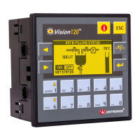
Describes the graphic LCD screen and 16-key keyboard used for operator interaction and data entry.
Explains the on-board I/O configurations and the use of I/O expansion modules for extended capacity.
Details the serial communication ports (RS232/RS485) and CANbus networking options available.
Discusses PLC and HMI application programming using VisiLogic software.
Outlines how the PLC application performs automation tasks with memory details.
Explains how to customize the operator interface with text, graphics, and variables.
Lists available data types (MB, MI, ML, MF, T, C, I, O) used in VisiLogic programming.
Highlights crucial safety precautions and warnings specific to this chapter's content.
Guide to checking controller kit contents and preparing for installation procedures.
Specifies conditions to avoid and safety measures for controller installation, like dust, heat, and wiring.
Step-by-step instructions for panel mounting, including cut-out dimensions and bracket usage.
Instructions for mounting the controller onto a standard DIN rail, including proper positioning.
Details the need for an external 12 or 24VDC power supply and circuit protection.
Crucial safety warnings related to live wires, earthing, voltage, and correct wiring practices.
Guidelines for stripping wires, using terminals, and proper torque for connecting the power supply.
Describes the variety of on-board I/O configurations available across different V120 models.
Explains how to connect I/O expansion modules to extend the controller's I/O capacity.
General guidelines for wiring I/O cables, avoiding interference and ensuring proper connections.
Details on-board I/O connection points and connectors for power, inputs, and outputs.
Describes the external connectors at the top and bottom of the controller for I/O connections.
Covers stripping wires, terminal insertion, and ensuring proper connection for I/O wiring.
Specifies wire gauge (26-14 AWG) and torque limits for I/O wiring to prevent damage.
Details technical specifications regarding specific I/O configurations available per model.
Explains digital input functionality, voltage levels, and pnp/npn configurations.
Describes how certain inputs can function as high-speed counters or shaft encoders.
Details the availability and types of analog I/O, including PT100 and thermocouple inputs.
Describes relay or transistor outputs and how digital output values are represented in programs.
Methods for protecting relay contacts and the controller from potential damage by inductive loads.
Instructions for integrating I/O expansion modules using an adapter and cable.
Details the two RJ-11 serial ports and their adaptation to RS232 or RS485 standards.
Details capabilities of RS232 for downloading programs and communicating with external devices.
Explains RS232 pin assignments and how to connect the controller to a PC via cable.
Covers using RS485 for multi-drop networks, pinout, and important caution notes.
Explains jumper settings for RS485 termination to function as an end device in a network.
Details how to configure jumpers to switch between RS232 and RS485 modes.
Step-by-step guide on safely opening the controller to access and change jumpers.
Describes CANbus for decentralized networks, specifications, and wiring considerations.
Lists CANbus speed options, max cable lengths, and power requirements.
Provides guidelines for using twisted-pair cables, network terminators, and grounding.
Instructions on how to enter and navigate Information Mode to view and edit controller data.
Overview of categories like Data Types, System, Function Blocks, and Hardware Configuration.
Details accessing system model, OS version, working mode, time/date, unit ID, and communication settings.
Information on viewing function blocks and setting a new password within Information Mode.
Displays status of I/O expansion modules and checks for short-circuited on-board or I/O modules.
Lists system bits, their functions, and whether they are read-only or writable.
Maps specific keypad keys to system bit (SB) values for programming.
Details system integers, their functions, and notes on writable parameters.
Lists system long integers and system double words, including their respective functions.
Explains PLCs as electronic control systems and their function in automated equipment.
Describes essential parts of a PLC: Operating Panel (HMI), Inputs, Outputs, and CPU.
Explains the PLC scan cycle (Read Inputs, Process Program, Send Outputs) and provides a simple ladder logic example.
| Brand | Unitronics |
|---|---|
| Model | Vision 120 OPLC |
| Category | Control Panel |
| Language | English |