Chapter 4: I/Os
17
Digital Outputs
Each controller contains either relay or transistor outputs. The digital output value is placed
in operand “O” when you write your program.
The power supply for transistor outputs requires an external circuit protection device. See
the technical specifications supplied with the controller.
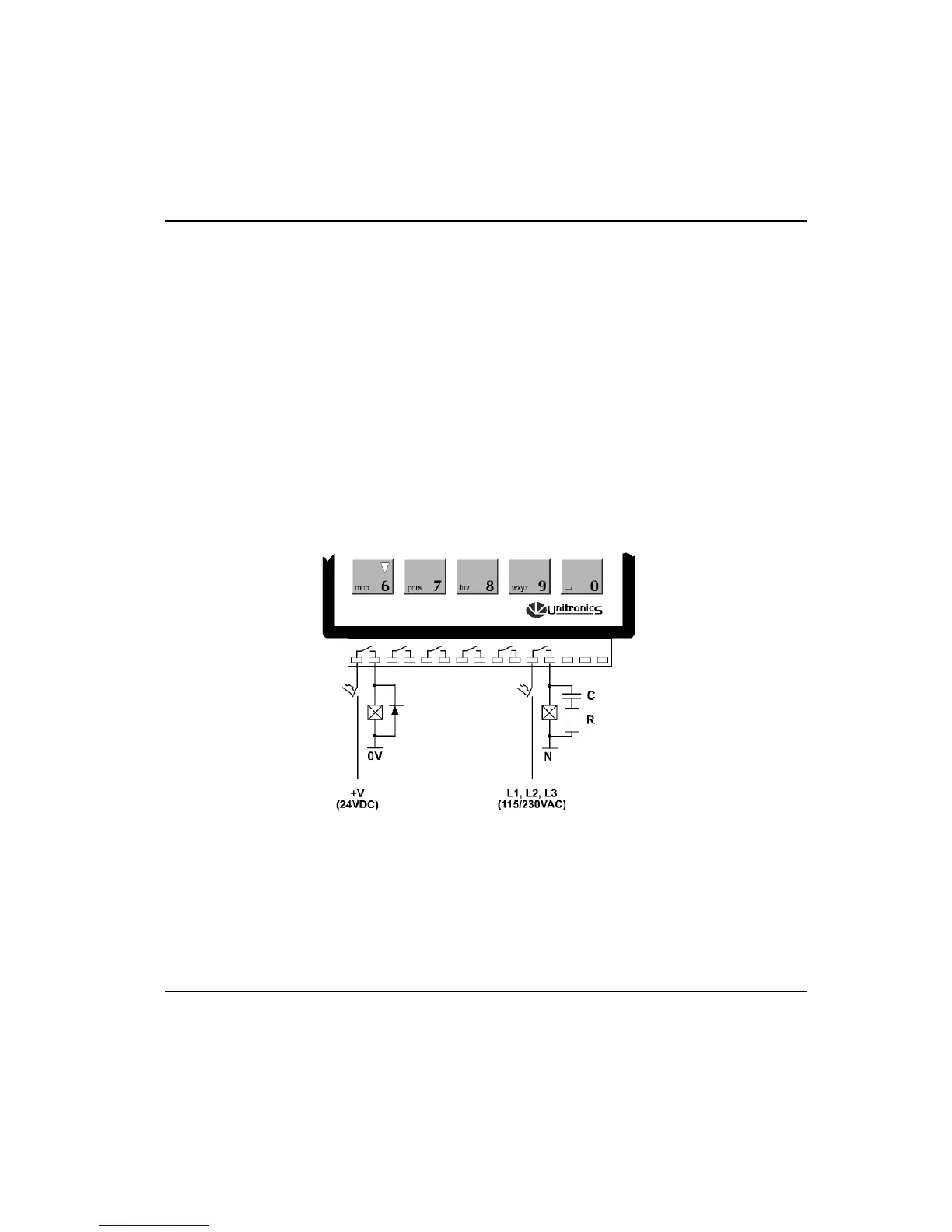
Relay Contact Protection
To increase the life span of your contacts and protect the controller from potential damage by
reverse-EMF, connect:
• a clamping diode in parallel with each inductive DC load
• an RC snubber circuit in parallel with each inductive AC load.
This is illustrated in Figure 8.
Figure 8. Increase the Contact Life Span
Installing I/O Expansion Modules
An adapter enables you to integrate I/O Expansion Modules into the system. You plug an
I/O expansion cable into the appropriate port located on the right side of the controller,
connect the cable to the adapter, and then plug I/O Expansion Modules into the adapter as
shown in Figure 9, page 18.