Vision120 OPLC™ User Guide
20
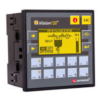
Table 1: RS232: Pinout
Diagram Pin Number RS232: Function
1 DTR signal
2 0V reference
3 TxD signal
4 RxD signal
5 0V reference
Pin #1
6 DSR signal
Note that standard programming cables do not provide connection points for pins 1 and 6.
In addition, note that when a port is adapted to RS485, Pin 1 (DTR) is used for signal A, and
Pin 6 (DSR) signal is used for signal B as shown in Table 2.
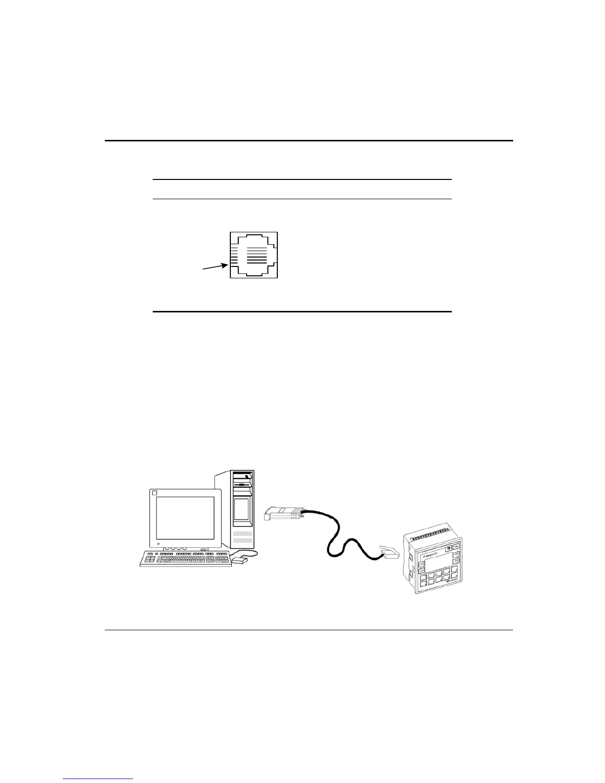
Downloading Your Program
You can download programs via a direct cable connection between your PC and the
controller. The cable should not exceed 3 meters in length.
Connecting the Controller to the PC
• Connect the controller to your PC using the communication cable as shown in
Figure 10.
Figure 10. Connecting the PC to the Controller