Vision120 OPLC™ User Guide
14
We recommend that you use crimp terminals for wiring; use 26-14 AWG wire for all wiring
purposes.
1. Strip the wire to a length of 7±0.5 mm (0.250–0.300 inches).
2. Unscrew the terminal to its widest position before inserting a wire.
3. Insert the wire completely into the terminal to ensure a proper connection according to
the figure below.
4. Tighten enough to keep the wire from pulling free.
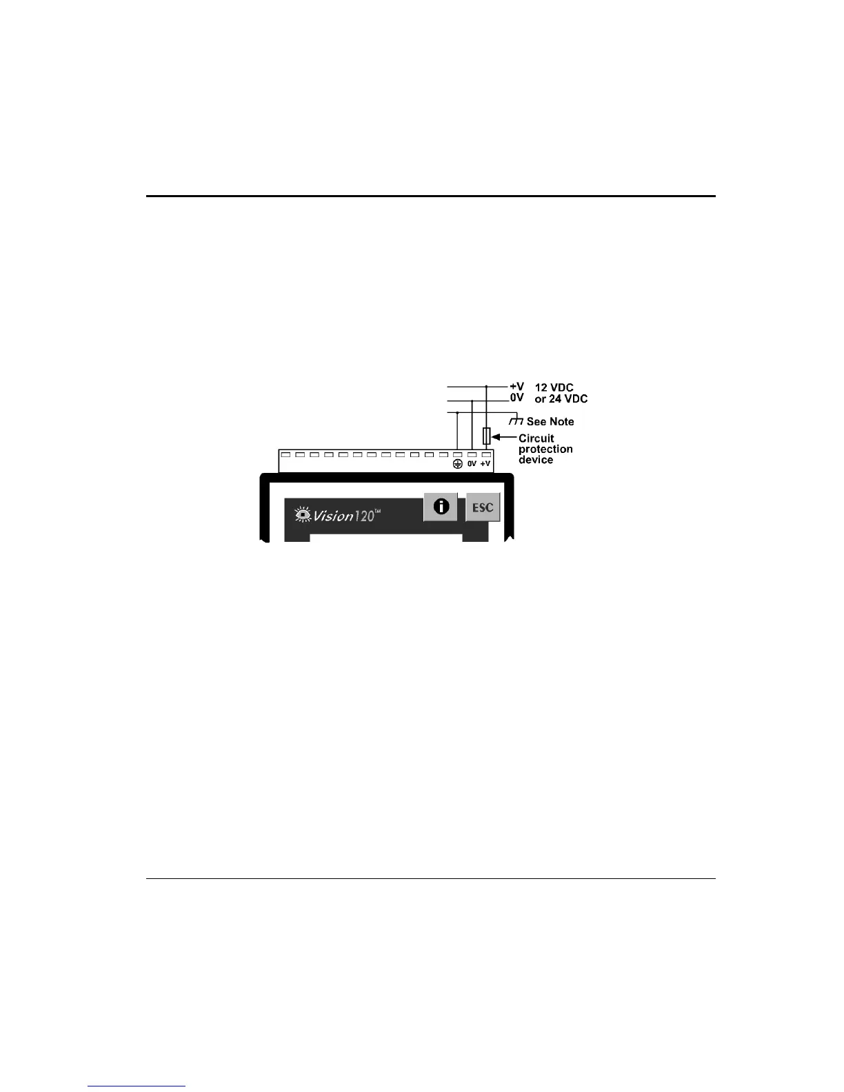
Figure 7. Power Supply Wiring
Earthing the Power Supply
To maximize system performance, avoid electromagnetic interference by
• Mounting the controller on a metal panel.
• Earthing the controller’s power supply: connect one end of a wire, 14 AWG, to the
chassis signal; connect the other end to the panel.
Note: The wire used to earth the power supply must not exceed 10 cm in length. If your
conditions do not permit this, do not earth the power supply.