EasyManuals Logo

Universal Robots E Series Service Manual

Universal Robots E Series
205 pages
To Next Page IconTo Next Page
To Previous Page IconTo Previous Page
Page #146 background image
All rights reserved 146 Service Manual e-Series (EN) 1.1.8
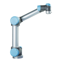
8.1 Robot Arm
Click on the page no. in the right column to see part in detail or go to the page.
NO.
DESCRIPTION
PART NUMBER(S)
PAGE NO.
1
Sealing ring set
103703/103705/103700
147-149
2
Lid set
103413/103405/103410
150-152
3
Protective cap for tool connector
131095
153
4
Tool mount with Force/Torque sensor
124083/124085/124080
154-156
5
Wrist joint 3
124002/102414/102412
157-159
6
Wrist joint 2
124110/124111/124112
160-162
7
Wrist joint 1
124001/102413/102411
163-165
8
Lower arm assembly
N/A
166
9
Elbow joint
124011/124031/124031
167-169
10
Upper arm
N/A
170
11
Shoulder joint
124021/124031/124041
171-173
12
Base joint
124021/124031/124041
174-176
13
Base with Robot Arm cable
122083/122085/122080
177-179
Refer to Section 4.1 Robot Arm for joint name and size.

Table of Contents

Other manuals for Universal Robots E Series

Questions and Answers:

Universal Robots E Series Specifications

General IconGeneral
Degrees of Freedom6
IP RatingIP54
ProgrammingPolyscope graphical user interface
Payload3 kg, 5 kg, 10 kg, 12.5 kg, 16 kg (depending on model)
Reach500 mm to 1300 mm
Joint Range± 360º (all joints)
Operating Voltage100-240 VAC, 50-60 Hz
Communication InterfacesEthernet
Safety StandardsISO 10218-1, ISO/TS 15066
Repeatability+/- 0.03 mm (UR3e, UR5e, UR10e, UR16e)

Related product manuals