EasyManuals Logo
Home>Universal Robots>Robotics>E Series

Universal Robots E Series Service Manual

Universal Robots E Series
205 pages
To Next Page IconTo Next Page
To Previous Page IconTo Previous Page
Page #137 background imageLoading...
Page #137 background image
All rights reserved 137 Service Manual e-Series (EN) 1.1.8
6.4 LED indicators and Fuse on Safety Control Board
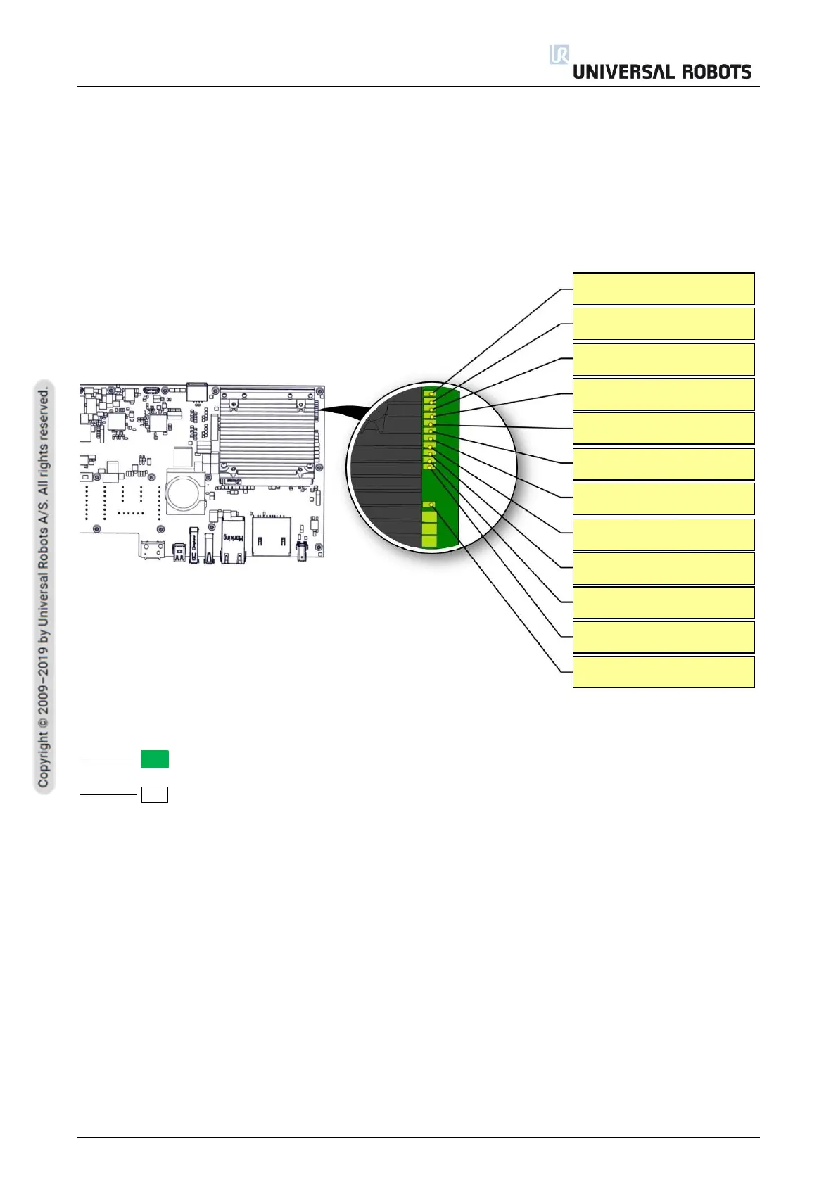
6.4.1 LED Indicators on Safety Control Board
The below LEDs are “power” LEDs. They are either on or off.
LED for power
Green permanent = Power on
No color permanent = Error or no power
+24V
+12V
+12V AUX
+5V
+5V PC
+3.3V Safety A
+3.3V Safety B
+3.3V FPGA
+3.3V PC
-4V for Analog
+1.8V/+2.5V FPGA
+48V Teach Pendant

Table of Contents

Other manuals for Universal Robots E Series

Questions and Answers:

Question and Answer IconNeed help?

Do you have a question about the Universal Robots E Series and is the answer not in the manual?

Universal Robots E Series Specifications

General IconGeneral
BrandUniversal Robots
ModelE Series
CategoryRobotics
LanguageEnglish

Related product manuals