6.4. LED indicators and Fuse on Safety Control Board
6.4.1. LED Indicators on Safety Control Board
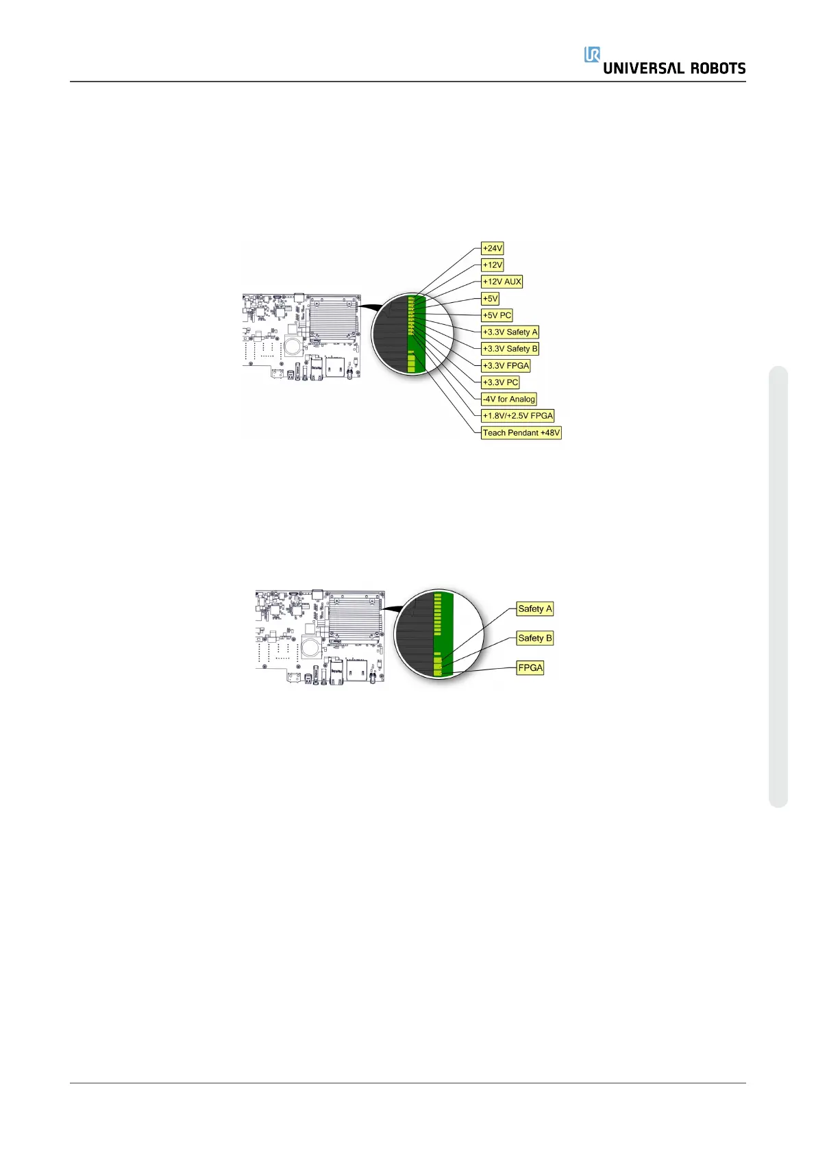
The below LEDs are “power” LEDs. They are either on or off.
LED for power
•
Green color permanent = Power on
•
No color permanent = Error or no power
Below are “communication” LEDs. They flash in different patterns, depending on the status.
LED for Safety A and Safety B
Green fast flash = Bootloader
Green slow flash = Normal communication
Red permanent = Error (Red flash can happen during bootup/power on, this is normal.)
LED for FPGA
Green/Red permanent = Normal communication
Green slow flash = No communication/trying to establish communication
6.4.2. Fuse
Fuse is a 10A fast-acting mini blade fuse.
Service Manual 93 e-Series
6.Troubleshooting
Copyright © 2009–2024 by UniversalRobotsA/S. All rights reserved.

 Loading...


