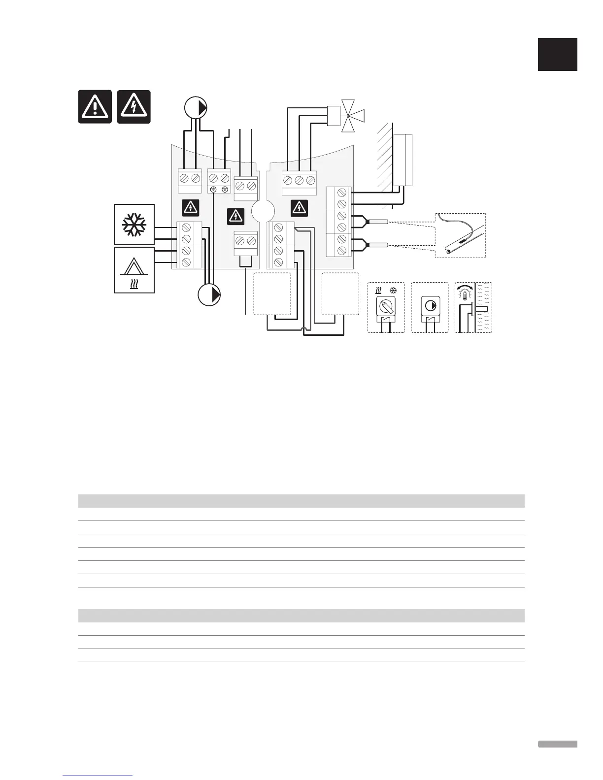
13.4 Controller wiring diagram
230 V AC
50 Hz
POWER
N
PUMP P1
PUMP P2 **
CONTACT
Ther ****
OUTSIDE *
WATER RETURN *****
In1/In2 ***In1/In2 ***In1/In2 **
WATER IN
SENSORS
SENSORS
HEAT COLD **
ACTUATOR 230 V
N
L
2
4
In2
In1
In1 In2
L
N
L
N
L
Open
Common
Close
230 V 50 Hz
230 V 50 Hz
230 V 50 Hz
230 V 50 Hz
*) The outdoor temperature sensor can be connected to either the controller or to a thermostat.
**) Connect either COLD or PUMP P2 (secondary heating/cooling circuit) to the connection terminal.
***) Select one of the inputs (heating/cooling switch, pump control signal, or immersion thermostat) and set parameter 11 – Wired Input 1 selection, or parameter 12 – Wired
Input 2 Selection, accordingly. The heating/cooling option can only be used in systems without a registered wireless thermostat.
****) Optional temperature limiter connection, fitted with a cable bridgre from the factory. Remove the bridge if a temperature limiter is to be used together with PUMP P1.
*****) Optional return sensor. Can only be used in systems without a registered wireless thermostat.
13.5 Reference data for sensors
Reference value for sensors
Check with an ohmmeter. The sensor must be unplugged
Temperature (
o
C) Resistance (Ohm) Temperature (
o
C) Resistance (Ohm)
-20 ~ 94 kΩ 40 ~ 5.3 kΩ
-10 ~ 54 kΩ 50 ~ 3.6 kΩ
0 ~ 32 kΩ 60 ~ 2.5 kΩ
10 ~ 20 kΩ 70 ~ 1.8 kΩ
20 ~ 12.5 kΩ 80 ~ 1.3 kΩ
30 ~ 8 kΩ
Sensor data
Sensor
Outdoor temperature CTN 10 kΩ at 25 °C (class II, IP55)
Supply water temperature CTN 10 kΩ at 25 °C (class I, IP68, no coupling)
Return water temperature CTN 10 kΩ at 25 °C (class I, IP68, no supply)
UK
CZ
DE
DK
EE
ES
FI
FR
HR
HU
IT
LT
LV
NL
NO
PL
PT
RO
RU
SE
SK
73
UPONOR SMATRIX MOVE/MOVE PLUS
·
INSTALLATION AND OPERATION MANUAL