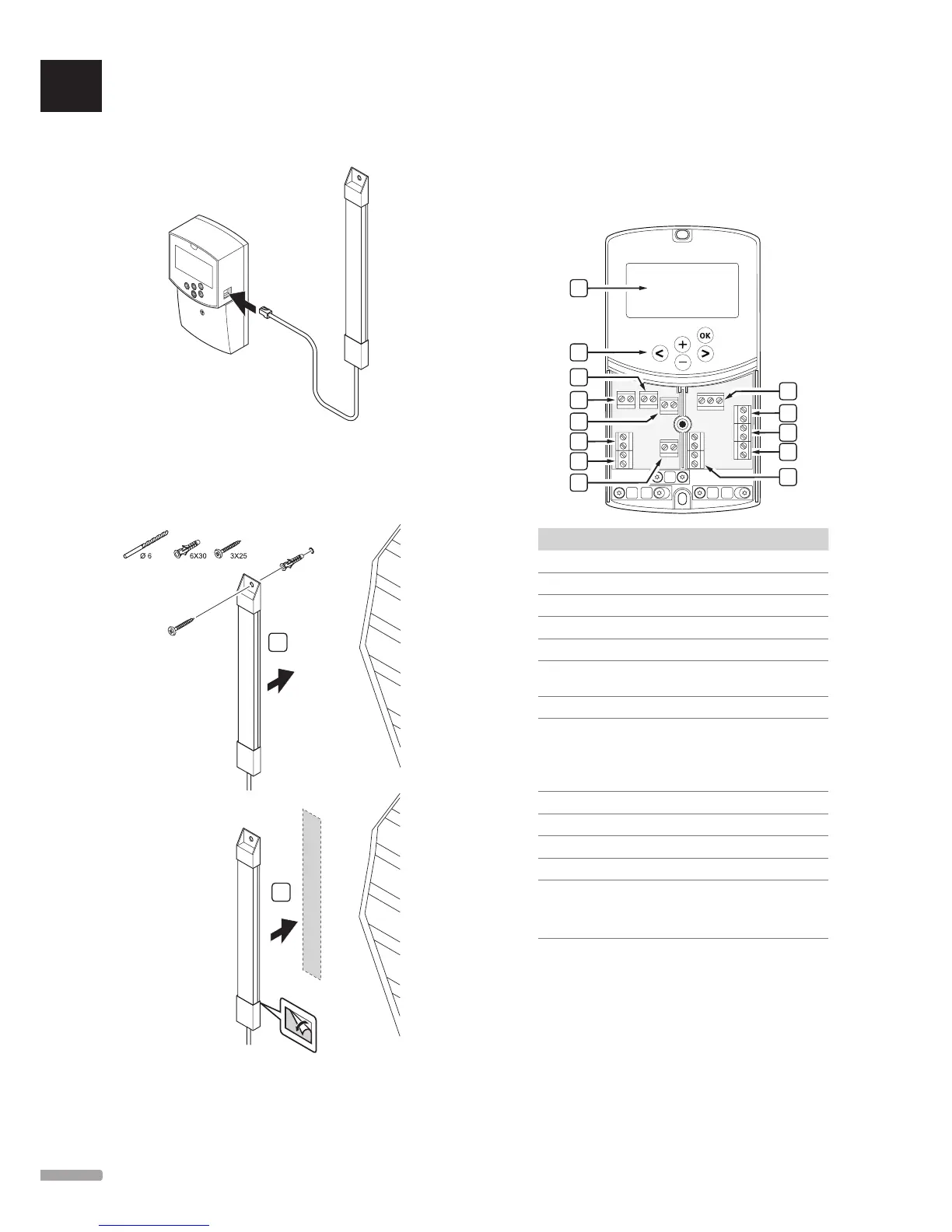
Connect the antenna cable
The illustration below shows how to connect the
antenna to the controller.
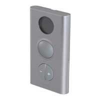
Attach antenna to the wall
The illustration below shows the antenna attached to
the wall with screws (A) or double-sided adhesive strips
(B).
A
B
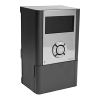
5.4 Connect components to controller
Prior to connecting a component, study the wiring
diagram, in the end of the manual, or the printed
circuit board in the controller, to locate the connector
positions. The illustration below shows the controller
with removed cover.
A
B
D
F
G
L
J
C
E
I
M
H
K
Item Description
A Display
B Buttons
C Terminal block, earth
D Terminal block, circulation pump, mixing circuit 1
E Terminal block, power supply
F Terminal block, cooling output or various
applications
G Terminal block, heating output
H Terminal block, optional temperature limiter
Fitted from the factory with a cable bridge, which
must be removed before connecting a temperature
limiter
I Terminal block, valve actuator
J Terminal block, outdoor sensor
K Terminal block, return temperature sensor
L Terminal block, supply temperature sensor
M Terminal block, wired inputs 1 and 2
Optional immersion thermostat or external
heating/cooling signal
UK
CZ
DE
DK
EE
ES
FI
FR
HR
HU
IT
LT
LV
NL
NO
PL
PT
RO
RU
SE
SK
20
UPONOR SMATRIX MOVE/MOVE PLUS · INSTALLATION AND OPERATION MANUAL