Communications vacon • 15
Local contacts: http://drives.danfoss.com/danfoss-drives/local-contacts/
6
NOTE! 2004 - 2007 can set as PID Control Reference by setting P15.1(Setpoint selection) or PID
Actual value by setting P15.4 (Feedback value selection)!
2004 - 2007 can be set as the Analogue Output by P9.1, P9.5, P9.9.
2004 - 2008 can set as Aux Control Word with P10.9:
b0: Run enable
b1: acc / dec ramp 2 selection
b2: freq reference 2 selection
NOTE!
• AUX CW is active when configured, even if control place is not the fieldbus
• b0 Run enable is computed in AND with a possible Run enable signal from digital input. Fall
of enable will cause coasting stop.
Status word (output process data)
Information about the status of the device and messages is indicated in the Status word. The Status
word is composed of 16 bits the meanings of which are described in the table below:
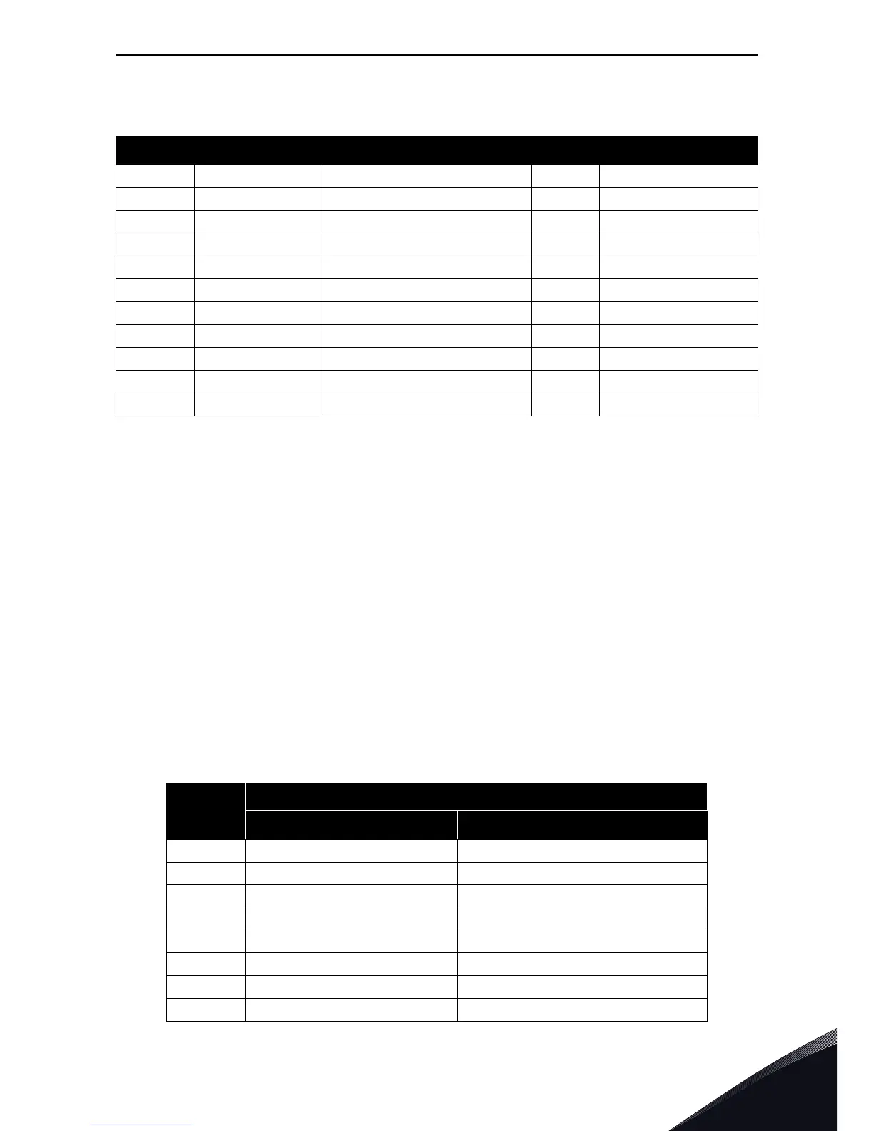
Table 9. Input process data
ID Modbus register Name Scale Type
2001 32001, 42001 FB Control Word Binary coded
2002 32002, 42002 FB General Control Word Binary coded
2003 32003, 42003 Actual speed 0.01 %
2004 32004, 42004 Programmable by P10.9
2005 32005, 42005 Programmable by P10.9
2006 32006, 42006 Programmable by P10.9
2007 32007, 42007 Programmable by P10.9
2008 32008, 42008 Programmable by P10.9
2009 32009, 42009 - - -
2010 32010, 42010 - - -
2011 32011, 42011 - - -
Table 10. Status word (output process data)
Bit
Description
Value = 0 Value = 1
B0, RDY Drive not ready Drive ready
B1, RUN Stop Run
B2, DIR Clockwise Counter-clockwise
B3, FLT No fault Fault active
B4, W No alarm Alarm active
B5, AREF Ramping Speed reference reached
B6, Z - Drive is running at zero speed
B7 - B15 - -

 Loading...


