MAIN CIRCUIT Service Manual M4 - M10
29.12.1999 Page 68
Irpre
Rdis
Rdis
t1
K1
Prpre
t1
t0
t1
Udc-bus
t0
t1
Ic
t0
t0
R
charging
Char.
relay
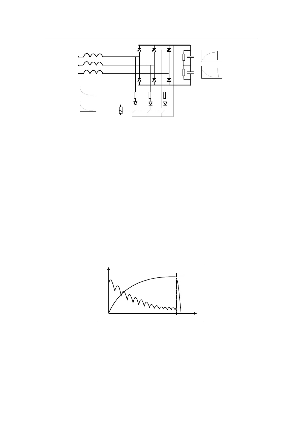
Figure 8.7 Charging circuit by semiconductive bridge and charging relay.
8.3.2 Operation
The DC capacitors in DC bus are being charged through precharging
resistor(s), from the moment of powering up a drive, to avoid capacitors´ life
threatening surge current. The charging current from two or three input
phases is lead through precharging resistor(s) by using charging contactor
with diode bridge or semiconductive brigde with charging relay.
The capacitor will be precharged via resistor(s), until energy in DC bus has
rosen on the level, which corresponds 85% of nominal dc voltage level.
=> Unominal (AC)*1.35*0.85 = charging switch will be closed.
On the next figure 8.8, the charging switch is closed in the moment (t1), the
precharging resistor is out of circuit and full three phase power is lead to DC
bus. At the same time (t1) circuit becomes low impedance, which causes DC
voltage to jump up with charging surge current in circuit.
Icapacitor
Udc-bus
t0
t1
Figure 8.8 DC voltage and precharging current.
In electricity outage the charging switch will be opened and it remains to open
if voltage in DC bus is dropped below 64%. If electricity return before the DC
bus is discharged to the level below 65%, the charging switch is still closed
thus it causes some amount of surge current from the line.