PC BOARDS Service Manual M4 - M10
22.10.2001 Page 122
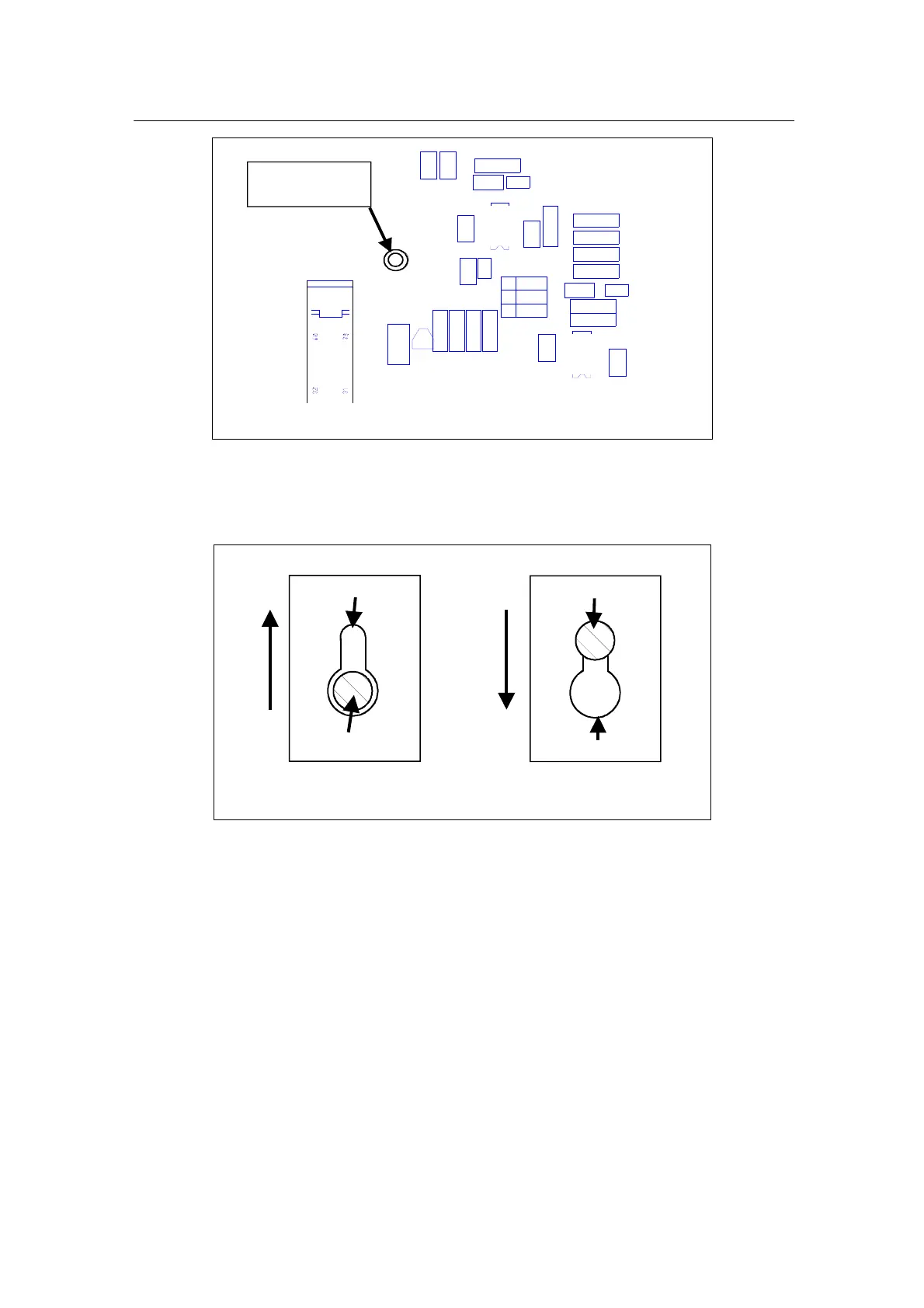
Location of
Fastening screw
C1
C2
C4 7
C4 8
C64
C6 5
C6 6
N1
N2
R3
R6
R1 2
R1 4
R1 5
R1 6
R1 7
R1 8
R21
R23
R24
R25
R26
R27
R2 8
R2 9
R30
S1
S2
S3
V2
X1 0
Location of the fastening screw on Expander board
5. Slide the board along guiding slots machined to standoffs, until the
board is released and can be pulled out from a drive, while the
standoffs slides through keyholes in the board.
Standoff
Keyhole in PCB
Slide the board up for releasing
Slide the board down for locking
Keyhole in PCB
Standoff
Mounting of PCB on standoffs
7. Before to assemble a new Expander board into the drive do all the
required settings to the board according to instructions in 9.6.7.
Assemble the board into drive in reversed order of the procedure
above.
8. Check all the connections and order of the wire harnesses plugged into
connectors.
9.6.9 Spare parts
Extender boards and resistor kits.
Detailed information for the spare parts is available from spare parts lists in
section “SPARE PART LIST”.