PC BOARDS Service Manual M4 - M10
22.10.2001 Page 90
9.2.7 Replacement of the Power Boards
1. Perform items 1 - 9 in the case of “REPLACEMENT OF THE CONTROL
BOARD”. In construction M4, remove side plates for easyer reaching
into electronics in the drive.
2. Carefully remove isolator located on the Power board.
3. In case of units in mechanical constructions M8 - M10, remove the
Branching board from connector X2 on the Power board.
4. Disconnect wire harnesses from connectors on the Power board.
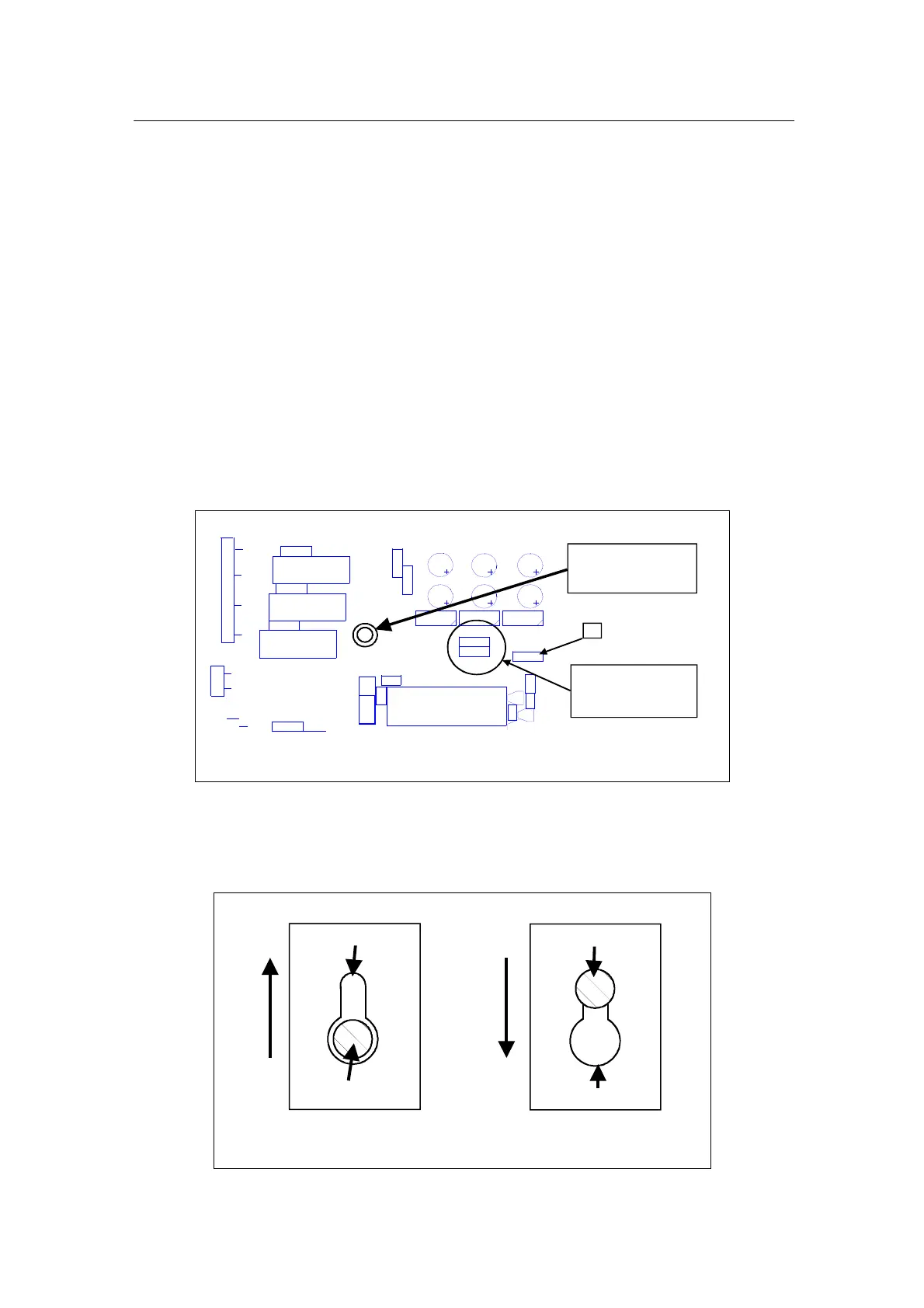
5. Remove a fastening screw to release the Power board. Location of the
screw is pointed out on layout drawings of the Power boards. Below is
a partial picture of the board to locate position of the fastening screw.
C14
C15
C16
C2 2 C2 3
C2 4 C2 5
C2 6 C2 7
C4 8
C52
D9
D1 1
D13
H18
R7
R9
R1 0
R1 3
R18
R7 2
R1 0 2
R109
R110
R1 11
R1 19
V59
V60
X1
X5
X6
X7
X8
X19
Voltage programming
resistors (R9, R18)
R18 placed on =>400V
R9 placed on =>500V
1
3
5
7
1
2
1
X1
Location of
Fastening screw
Location of the fastening screw on Power board
7. Slide the board along quiding slots machined to standoffs, until the
board is released and can be pulled out from a drive, while the
standoffs slides through keyholes in the board.
Standoff
Keyhole in PCB
Slide the board up for releasing
Slide the board down for locking
Keyhole in PCB
Standoff
Mounting of PCB on standoffs