MAIN CIRCUIT Service Manual M4 - M10
29.12.1999 Page 73
8.6 Mechanics
8.6.1 Bus bars
Assembly instruction’s helps to place bus bars to a right order and to connect
discharging (balancing) resistors after repair.
Frame: Drawing no:
M8 690V JS001
M9 690V JS002
M10 690V JS003
Plastic capacitors must be installed (clued) on top of the DC bus bar (between
DC- and DC+).
Ordered spare bus bar, capacitors are already fixed.
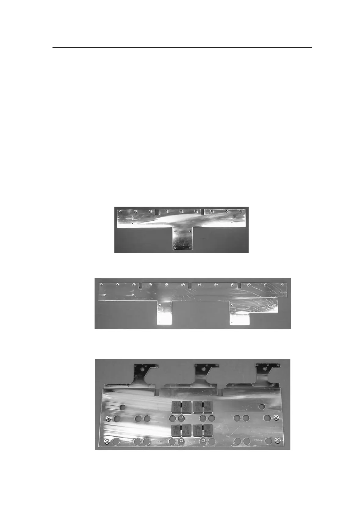
See following images to identify bus bar components:
Picture 8.6.1.1. MC09039, M9 690V DC+ bus bar
Picture 8.6.1.2. MC10027, M10 690V DC+ bus bar
Picture 8.6.1.3. MC09054, M9 690V DC bus bar with capacitors