MAIN CIRCUIT Service Manual M4 - M10
29.12.1999 Page 77
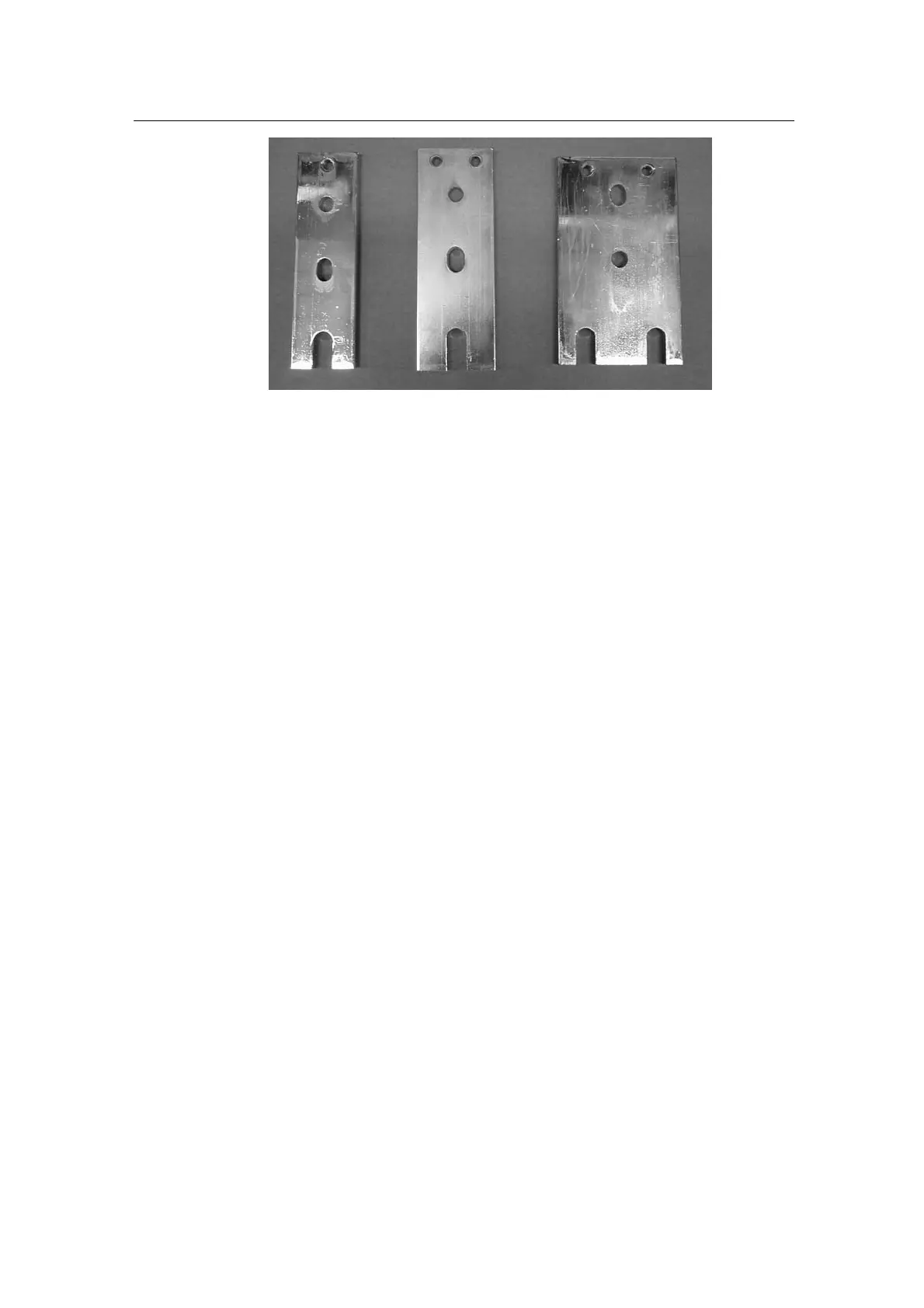
Picture 8.6.2.2. Input terminals
Left: MC08122
Middle: MC09022
Right: MC10022
8.7 Connectors
Check connectors and pay attention mainly on possible corrosion, light arc
marks and the proper tightening torque. Refer torque specifications in
appendix 17.3.
8.8 NTC resistor
NTC resistor is mounted to heat sink by using metal glue. In multiple block
units each block has its own temperature measurement and NTC resistor. For
fault tracing the resistance values can be found in separate section, (17).
8.9 Main circuit diagrams
The copies main circuits are attached to the end of this section. The main
circuit diagrams are presented by frame sizes and voltages.
The CX4 and CX5 main circuits are exactly same for both voltages. The CX2
main circuit is same for all power sizes of the CX2 -series. The CX6 main
circuits are presented for all mechanical sizes.