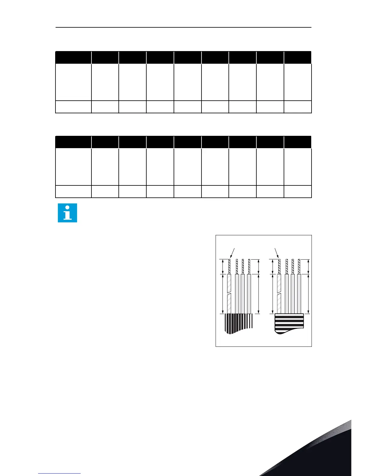
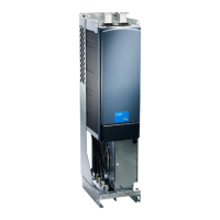
Table 36: The cable stripping lengths [mm]. See the figure in step 1.
Frame A1 B1 C1 D1 A2 B2 C2 D2
FR8
0140
0168—0205
23
28
240
240
23
28
240
240
23
28
240
240
23
28
240
240
FR9 28 295 28 295 28 295 28 295
Table 37: The cable stripping lengths [in]. See the figure in step 1.
Frame A1 B1 C1 D1 A2 B2 C2 D2
FR8
0140
0168—0205
0.91
1.10
9.45
9.45
0.91
1.10
9.45
9.45
0.91
1.10
9.45
9.45
0.91
1.10
9.45
9.45
FR9 1.10 11.61 1.10 11.61 1.10 11.61 1.10 11.61
NOTE!
If you want to connect an external brake resistor, see Brake Resistor Manual. See
also Chapter 7.9.7.1 Internal brake resistor connection (P6.7.1).
1 Strip the motor cable, the mains cable, and the
brake resistor cable.


 To Next Page