NOTE!
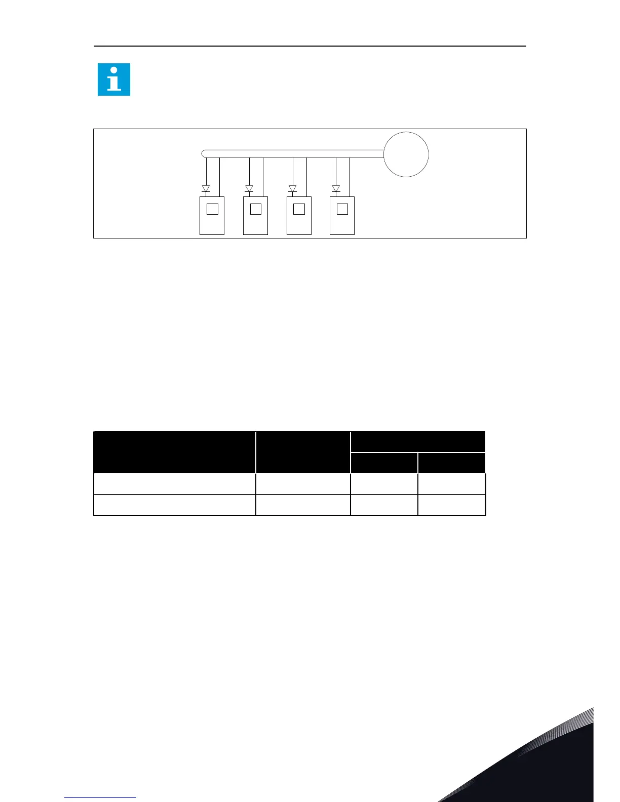
If the 24 V inputs of many AC drives are connected in parallel, we recommend that
you use a diode in terminal #6 (or #12) to prevent the current to flow in opposite
direction. This can do damage to the control board.
Fig. 21: Parallel connection of 24 V inputs with many AC drives
6.2 CONTROL UNIT CABLING
The OPTA1 basic board has 20 control terminals, and the relay board has 6 or 7. You can see
the standard connections of the control unit and the descriptions of signals in Fig. 22.
6.2.1 SELECTION OF THE CONTROL CABLES
The control cables must be a minimum of 0.5 mm
2
(20 AWG) screened multicore cables. See
more on the cable types in Table 23 The selection of the correct cable. The terminal wires must
be a maximum of 2.5 mm
2
(14 AWG) for the terminals of the relay board and 1.5 mm
2
(16
AWG) for other terminals.
Table 39: The tightening torques of the control cables
The terminal The terminal screw The tightening torque
Nm lb-in.
Relay and thermistor terminals M3 0.5 4.5
Other terminals M2.6 0.2 1.8
6.2.2 CONTROL TERMINALS
Here you see the basic description of the terminals of the I/O board and the relay board. For
more information, see 6.2.2.2 Jumper selections on the OPTA1 basic board. For more
information on control terminals, see All-in-One Application manual.
CONTROL UNIT VACON · 71
24-HOUR SUPPORT +358 (0)201 212 575 · EMAIL: VACON@VACON.COM
6

 Loading...


