Fig. 23: The control terminal signals on relay boards OPTA2 and OPTA3
6.2.2.1 Digital input signal inversions
The active signal level is different when the common inputs CMA and CMB (terminals 11 and
17) are connected to +24 V or to ground (0 V). See Fig. 24.
The 24 V control voltage and the ground for the digital inputs and the common inputs (CMA,
CMB) can be internal or external.
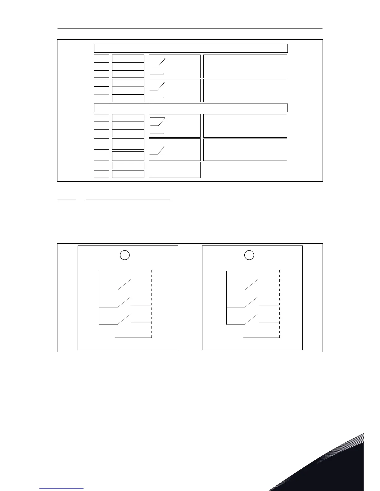
Fig. 24: The Positive/Negative logic
A. Positive logic (+24 V is the active signal)
= the input is active when the switch is
closed.
B. Negative logic (0 V is the active signal) =
the input is active when the switch is
closed. You must set the jumper X3 to
the position 'CMA/CMB isolated from
ground'.
CONTROL UNIT VACON · 73
24-HOUR SUPPORT +358 (0)201 212 575 · EMAIL: VACON@VACON.COM
6