26 Instructions for installation and servicing ecoTEC 839592_12
4.14.2 Connection to the main supply
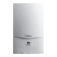
Fig. 4.13 Opening the electronics box
• Remove the front case and lower the control panel.
• Unclip the bottom of the terminal box cover and hinge
back to reveal the connection plugs.
• Feed the power supply flex into the appliance and the
control panel through the cable clamps provided and
tighten.
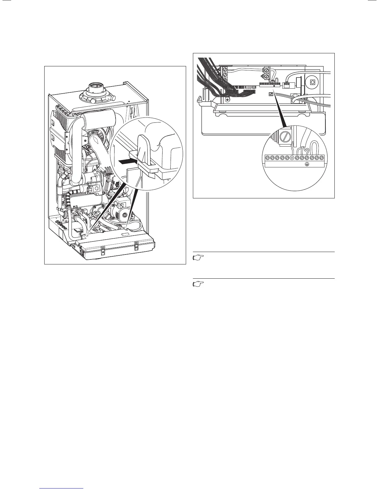
-+789 LN 345
Fig. 4.14 Wiring system
• Connect the flex to the L, N and earth plug to the
terminal block.
Green/yellow (earth) wire – boiler terminal Earth sign
Blue (neutral) wire – boiler terminal N
Brown (live) wire – boiler terminal L
Note
Do not connect any power voltage to the
connections 7-8-9 or BUS (+,-).
Note
Ensure that the wires are securely fixed in the
terminal block.
• Refit the terminal box cover by pushing into place
until it clips back into position.
• Raise the control panel.
4 Boiler installation sequence

 Loading...