8 Instructions for installation and servicing ecoTEC 839592_12
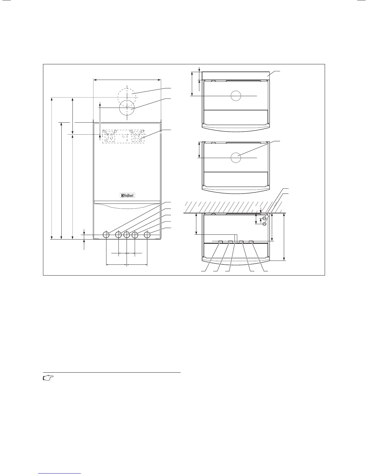
2.2 Dimensions
241
20
642
720
883
125
100100
440
35 35
130
180
300
ecoTEC plus 630:
334
ecoTEC plus 637,
ecoTEC plus 837:
368
175
190
65
75
45
8
6
4
3
2
1
5
7
10
9
12345
11
12
Fig. 2.1 Dimensions in mm
Legend:
1 Heating return pipe Ø 22 mm
2 Cold water connection Ø 15 mm (combination boilers only)
3 Gas connection Ø 15 mm
4 Hot water connection Ø 15 mm (combination boilers only)
5 Heating flow pipe Ø 22 mm
6 Hanging bracket
7 Flue hole - flue system 60/100
8 Flue hole - flue system 80/125
9 Spacer frame accessory (Art. No.: 308 650)
10 Flue pipe connection
11 Condensate drain connection (Ø 19 mm)
12 Heating system expansion relief valve connection (Ø 15 mm)
Note
With the spacer frame (Art. No 308 650), the
pipes can be run behind the boiler. The distance
of the appliance from the wall thus increases
by 65 mm.
2 Boiler specifications
 Loading...