27Instructions for installation and servicing ecoTEC 839592_12
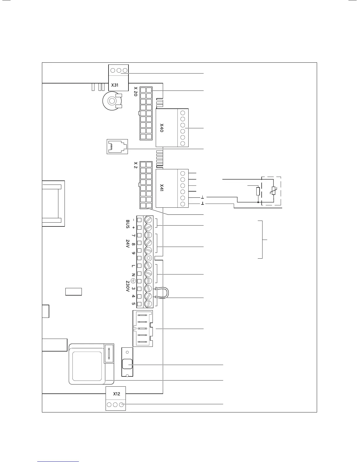
4.14.3 Electric board layout
Burner cable harness
Hydraulic cable harness
Connection for external
eBUS controller
Room thermostat 24 V:
Connection 7, 8 and 9
No bi-directional
interface (analogue only)
Room thermostat 230 V/50 Hz
(remove bridge on connection)
Heating pump
With ecoTEC pro: 1-step pump (plug with 3-pin)
With ecoTEC plus: 2-step pump (plug with 5-pin)
Mains supply: 230 V/50 Hz
2A fuse, slow
Igniter
Caution:
Do not connect
supply voltage!
Risk of damage
to electronics!
Diagnosis via eBUS,
vrnetDIALOG
Accessory module connection
outer probe
ext. flow or return probe
Connection: 230 V
Supply for accessory module
eBUS accessory connection
Fig. 4.15 Connection wiring ecoTEC
Boiler installation sequence 4

 Loading...