36 Instructions for installation and servicing ecoTEC 839592_12
Boiler
Nominal net heat
input in kW
as per BS EN 483
Gas flow rate
Natural gas in m
3
/h Propane in kg/h
nominal + 5% - 10% nominal + 5% - 10%
ecoTEC plus 612 12.2 1.29 1.36 1.16 0.95 1.00 0.85
ecoTEC plus 615 15.3 1.62 1.70 1.46 1.19 1.25 1.07
ecoTEC plus 618 18.4 1.95 2.04 1.75 1.43 1.50 1.29
ecoTEC plus 624 24.5 2.59 2.72 2.33 1.90 2.00 1.71
ecoTEC plus 630 30.6 3.24 3.40 2.91 2.38 2.50 2.14
ecoTEC plus 637 37.8 4.00 4.20 3.60 2.94 3.08 2.64
ecoTEC plus 824 23.5 2.49 2.61 2.24 1.83 1.92 1.64
ecoTEC plus 831 31.6 3.34 3.51 3.01 2.45 2.58 2.21
ecoTEC plus 837 37.8 4.00 4.20 3.60 2.94 3.08 2.64
ecoTEC pro 24 23.5 2.49 2.61 2.24 1.83 1.92 1.64
ecoTEC pro 28 28.6 3.03 3.18 2.72 2.22 2.33 2.00
Table 5.1 Gas flow rates
• If the measured gas flow rate lies outside the toler-
ance limits specified in Table 5.1, do not operate the
boiler and inform the Vaillant Service Solutions
(0870 6060 777).
If the measured gas flow rate is within the tolerance
limits shown in Table 5.1, then proceed as follows:
• Take the boiler out of operation by
- Pressing the + and i buttons simultaneously and
turn down both thermostat control knobs.
- Only for combination boilers: Allow the boiler to cool
down by turning off water taps and allow pump
overrun to operate for a minimum of two minutes.
• Record the boiler maximum gas flow rate onto the
Benchmark gas boiler commissioning checklist.
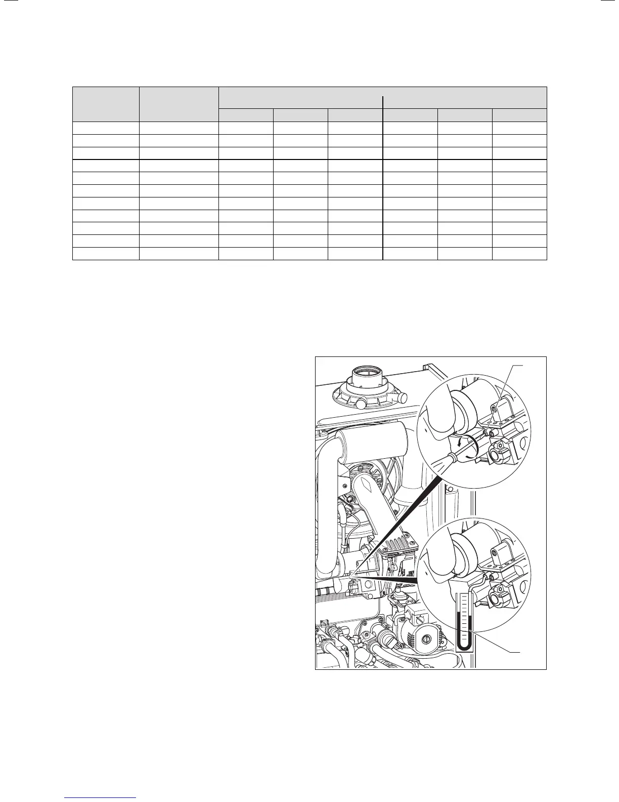
5.9.3 Checking the gas inlet working pressure
• Ensure that the gas inlet working pressure can be
obtained with all other gas appliances in the property
working.
• Remove the front casing from the boiler.
• Close the gas isolation valve of the boiler.
1
2
Fig. 5.8 Measuring the gas inlet working pressure
• Loosen the sealing screw marked “in” (1) on the gas
valve.
5 Commissioning Part I

 Loading...