54 Instructions for installation and servicing ecoTEC 839592_12
8.2 Test programs
Special functions can be triggered on the appliances by
activating various test programs.
These programs are given in detail in the Table 8.5.
• The test programs P.0 to P.6 will be started when
“Power ON” is turned on and the “+” key is pressed
for 5 s. The display shows “P.0”.
• Press the “+” key to start counting the test number
upwards.
• Press the “i” to operate the appliance now and to
start the test program.
• Press “i” and “+” simultaneously to exit the test
programs. You can also exit the test programs by not
pressing any key for 15 minutes.
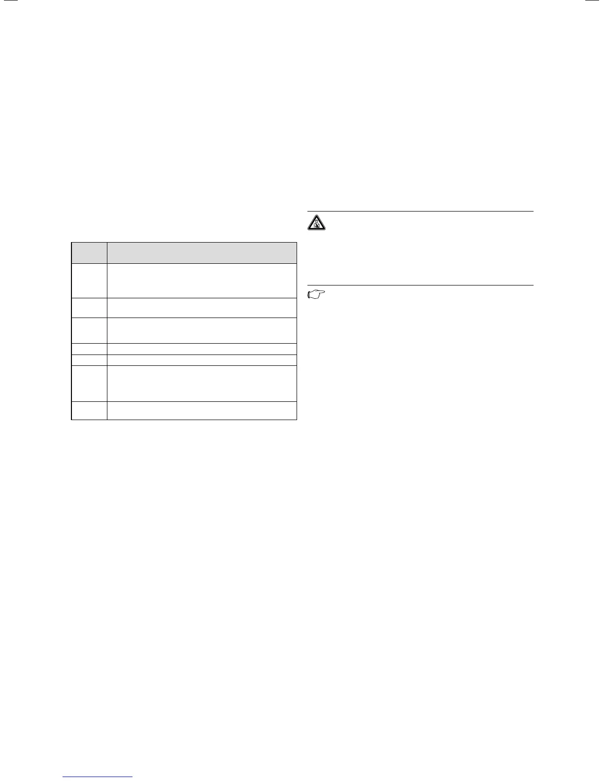
Display Meaning
P.0 Bleeding test program. The heating circuit and hot
water circuit (combination boiler only) is bled via the
automatic air vent (the cap on the automatic air vent
must be loosened).
P.1 Test program where the appliance is operated in full
load after successful ignition
P.2 Test program where the appliance is operated with
minimum gas volume (ignition gas volume) after suc-
cessful ignition
P.3 not available
P.4 not available
P.5 Test program for the safety temperature limit check;
appliance heats up by by-passing a regulating shut-
down through the flow regulator until the shutoff tem-
perature of 97 °C is achieved.
P.6 Filling test program. The diverter valve moves to the
centre position
Table 8.5 Test programs
8.3 Resetting parameter to factory settings
Besides the option to reset individual parameters
manually to the factory settings specified in Tables 8.2
and 8.3, you can also reset all parameters
simultaneously.
• In the second diagnostic level, under the diagnostic
number “d.96” change the value to 1 (see section 8.1.2).
The parameters of all adjustable diagnostic numbers
now correspond to the factory settings.
9 Parts replacement
The tasks listed below in this section may be carried out
only by a ompetent person approved at the time by the
Health and Safety Executive und in accordance with the
Gas Safety (Installation and Use) Regulations 1998.
• Only use genuine spare parts for repairs.
• Make sure the parts are correctly fitted and that their
original position and alignment are retained.
9.1 Safety instructions
Danger!
Each time the components are replaced, comply
with the safety instructions below for your own
safety and to avoid damage to the appliance!
• Put the appliance out of operation.
Caution!
Before starting any maintenance work:
Isolate the mains electricity supply by
disconnecting the plug at the socket outlet (if
there is only an isolating switch remove the
fuse from the switch).
• Close the service valve in the gas supply as well as the
service valves in the heating flow and return pipe.
• Close the service valve in the cold water supply line
(combination boilers only).
• Empty the appliance if you want to replace water-
bearing components of the appliance.
• Make sure that no water drops on live components
(e.g. switch box etc.).
• Use only new seals and O-rings.
• After completing the work, check for gas leaks and
perform a function check (see section 7.6).
• Always check earth continuity, polarity and resistance
to earth with a multimeter after any service work and
after exchanging any electrical component.
8 Troubleshooting
9 Parts replacement

 Loading...