9Instructions for installation and servicing ecoTEC 839592_12
2.3 Installation
1
2
3
4
6
5
7
8
9
14
13
11
10
12
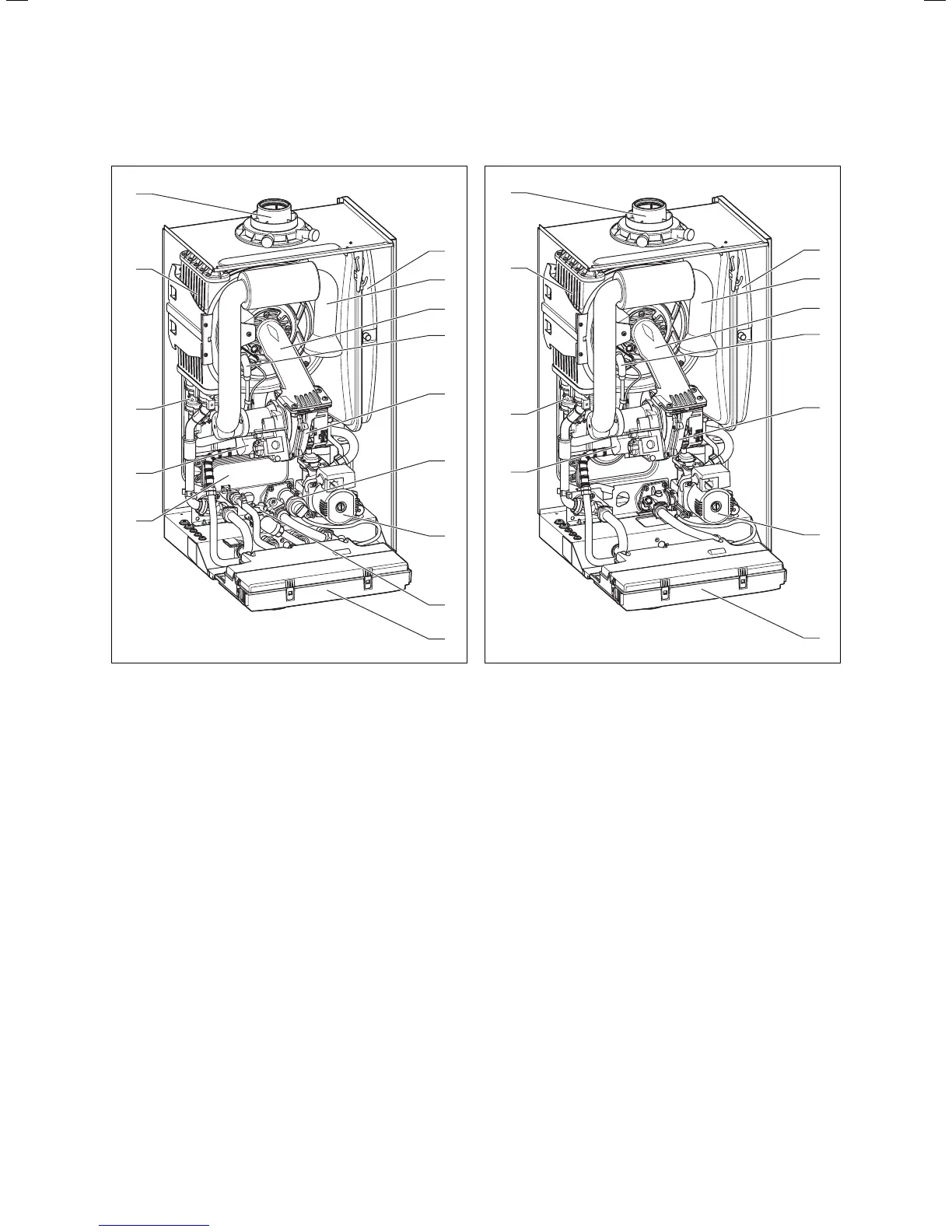
Fig. 2.2 Function elements of combination boilers
Legend:
1 Expansion vessel
2 Air intake pipe
3 Burner module
4 Ignition electrode
5 Fan
6 Diverter valve with by-pass
7 Pump
8 Aqua-Sensor
9 Electronics box
10 Hot water heat exchanger
11 Gas valve
12 Pressure sensor
13 Heat exchanger
14 Flue pipe connection
2.4 Type plate
The type plate of the Valliant ecoTEC is attached to the
bottom of the appliance at the factory.
1
2
3
4
5
7
9
14
13
12
11
Fig. 2.3 Function elements of system boilers
Legend:
1 Expansion vessel
2 Air intake pipe
3 Burner module
4 Ignition electrode
5 Fan
7 Pump
9 Electronics box
11 Gas valve
12 Pressure sensor
13 Heat exchanger
14 Flue pipe connection
Boiler specifications 2

 Loading...