14
PR-23 instrucon manual
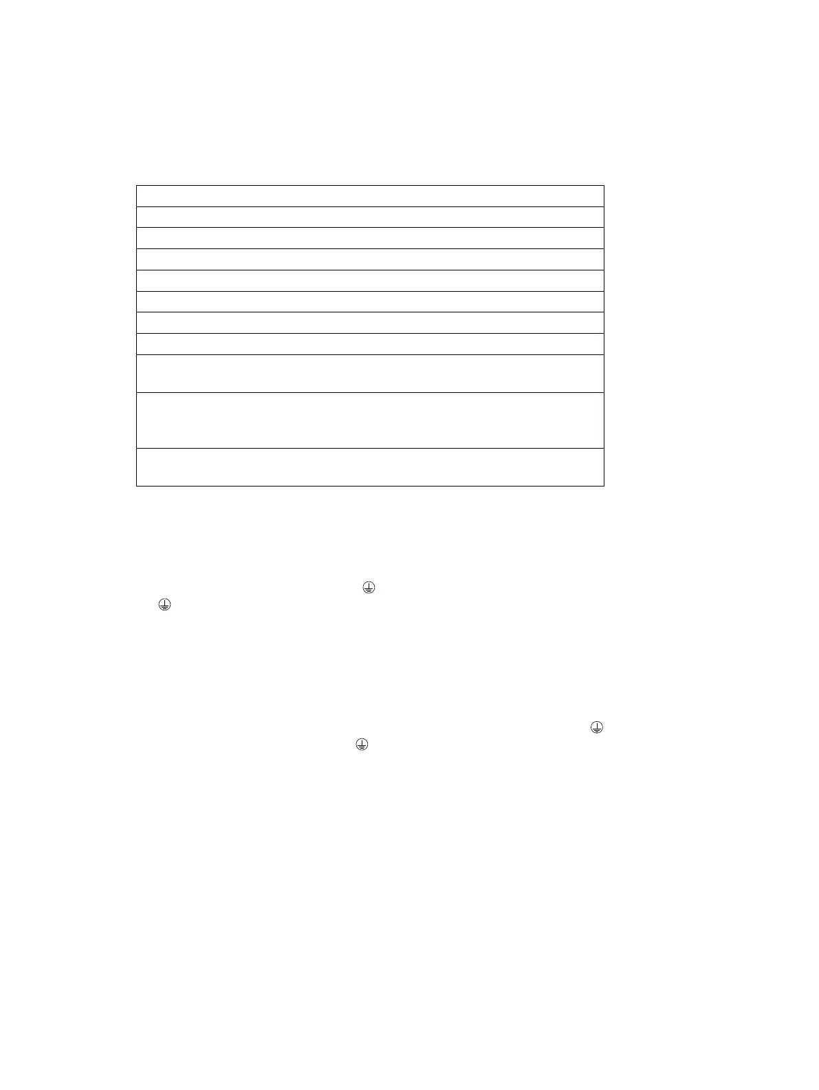
On H1
A 1 2 3 Connecon for Sensor A, signal wires (1, 2), cable shield (3).
B 1 2 3 Connecon for Sensor B, signal wires (1, 2), cable shield (3).
On Motherboard
11 12 4–20 mA output 1, posive (11), negave (12), max. load 1000 Ohm, galvanically isolated.
13 14 4–20 mA output 2, posive (13), negave (14), max. load 1000 Ohm, galvanically isolated.
21 22 Relay 1, one contact output, max. 250 V AC, max. 3 A.
23 24 Relay 2, one contact output, max. 250 V AC, max. 3 A.
31 32 33 Power, L (31), N (32), protecve earth (33), 100-240 V AC, 50–60 Hz. An external power switch
(Figure 3.6) is recommended.
41 42 24V terminal for DTR internal use only.
Note: Connecng terminal to external 24V supply will void warranty. Connecng external devices
to 24V terminal will void warranty.
51 52 53 54 55 Switch inputs: switch 1 (51), switch 2 (52), switch 3 (53), switch 4 (54) and common 3 volts for all
inputs (55). The switch terminals are galvanically isolated.
3.3.4 Power terminals for AC power
POWER
3.3.5 Power terminals for 24V DC power
POWER
3.3.6 Reset buon

 Loading...