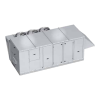
Dedicated Outdoor Air Unit 17
Airflow Monitor
A factory-wired, mounted, and powered airflow
monitoring system is provided in the outdoor and/or
exhaust air streams. The airflow control system offers
the following functionality:
• Display of outdoor and/or exhaust airflow rate in
actual cubic feet per minute (CFM) or actual liters per
second (LPS) on a 16 character LCD display.
• Two configurable analog outputs for transmitting
outdoor and/or exhaust airflow rate, outdoor air
temperature, or a proportional-integral-derivative
(PID) control signal based on an outdoor airflow set
point.
• A configurable digital output that operates based on
an airflow set point or range.
Operation
Outdoor and/or exhaust airflow monitoring is
accomplished using two thermal dispersion sensors
that accurately measure airflow velocity down to zero
feet per minute (fpm). The airflow controller takes the
average measurement for two sensor configurations,
and determines the outdoor airflow rate based on the
effective intake area. Field calibration of the outdoor
airflow monitoring device determines the effective intake
area of the unit.
For additional information on how to navigate through
the airflow controller menus, refer to technical manuals
from GreenTrol® Automation Inc. at www.greentrol.com.
Hot Gas Bypass Valve (standard scroll)
On units equipped with hot gas bypass, hot gas
from the compressor is injected into the liquid line of
the evaporator coil after the thermostatic expansion
valve. This process starts to occur when suction gas
temperatures drop below 28°F, which is 32°-34°F coil
surface temperature. Hot gas helps the evaporator coil
from freezing up and the compressor from cycling. The
valve needs to be adjusted to exact specifications once
unit is installed in the field.
Optional Component Operation
IMPORTANT
For the airflow monitoring device to perform as
intended, field calibration is required. Calibration of
the airflow monitoring device requires an independent
measurement of airflow and should be performed
when the system undergoes test and balance.
Hot Gas Reheat Valve
Units equipped with a reheat coil
use a three-way valve with actuator
to control the supply air discharge
temperature of the unit during
dehumidification mode. The unit
controller provides a 0-10VDC signal
to control the amount of reheat to
meet the supply temperature set
point.
Controls by Others
The reheat coil needs to be purged to ensure adequate
oil return. It is recommended that every six hours of
reheat compressor run time should initiate a six minute
purge cycle. During the purge cycle, the reheat valve
should be modulated to 100% open to the reheat coil.
VFD Compressor
If the VFD compressor option is included, the
compressor VFD is mounted in the end of the
condensing section. Condensing section internal
components are accessible via the access panel on the
side of the condenser coil.
Envelope Control
The unit controller tracks the operating point of the VFD
compressor within the operating envelope at all times. If
the operating point is out of the envelope, the controller
will take action to bring it back in. If unsuccessful, the
controller will shut down the compressor. DO NOT
operate the compressor VFD in hand mode because
the envelope control safeties will not be in place. Refer
to the controls IOM for more information on envelope
control.
Electronic Expansion Valve
An electronic expansion valve is provided on the VFD
compressor circuit to ensure tight superheat control
throughout the compressor modulation band. The EXV
acts as a liquid line solenoid valve when the compressor
is off to prevent refrigerant migration.
Crankcase Heat
The VFD compressor will be heated by the compressor
stator. To ensure optimal performance and reliability, do
not disable stator heat. All other compressors will be
provided with a crankcase heater.
Oil Return Management
The compressor VFD has an oil return purge cycle such
that if the compressor has been operating below a set
RPM for a set period of time, the VFD will accelerate the
compressor to ensure sufficient lubrication.
DO NOT disable the oil return management function.
DO NOT operate the compressor VFD in hand mode
because the oil return management will not be
operational.

 Loading...