Dedicated Outdoor Air Unit30
Sequence of Operation
Optional Economizer - The economizer will be locked
out when: the outside air is below economizer lockout;
the unit is operating in dehumidification mode; or there
is a call for heating.
• Stop Wheel: When economizer mode is enabled
and there is a signal for cooling, the wheel will stop
rotating to allow free cooling.
• Modulate Wheel: When economizer mode is
enabled and there is a signal for cooling, the
wheel VFD modulates wheel speed to maintain the
discharge temperature set point.
Optional Frost Control - The microprocessor controller
will output a signal when wheel frosting is occurring
which is determined by a temperature set point (OA
<5°F – 2°F hysteresis, adjustable) and wheel pressure
drop increase.
• Preheat: When frosting is occurring, the preheater
is energized to defrost the wheel. Once the
pressure drop decreases below the set point, the
preheater is de-energized.
• Modulating Wheel: Includes a VFD in addition
to the thermostat and pressure sensor. When
modulating wheel frost control is initiated, the VFD
will reduce the speed of the wheel, which keeps
the exhaust air condition from reaching saturation,
thus, eliminating condensation and frosting. If the
outdoor air temperature is greater than the frost
threshold temperature OR the pressure differential
is less than the set point, the wheel will run at
full speed. If the outdoor air temperature is less
than the frost threshold temperature AND the
pressure differential is greater than the set point,
the wheel will run at reduced speed until the
pressure differential falls below the set point. The
temperature and pressure differential set points are
set at the factory, but are field-adjustable. The VFD
will be fully programmed at the factory.
Optional Energy Wheel
Start-Up
If selected, the energy wheel is installed in the unit’s
airstream with one half of the wheel in the intake
airstream and one half in the exhaust airstream. Air
leakage between the two airstreams has to be kept to
a minimum and the wheel has air seals that must be
adjusted for that purpose. The seals must be adjusted
at time of start-up.
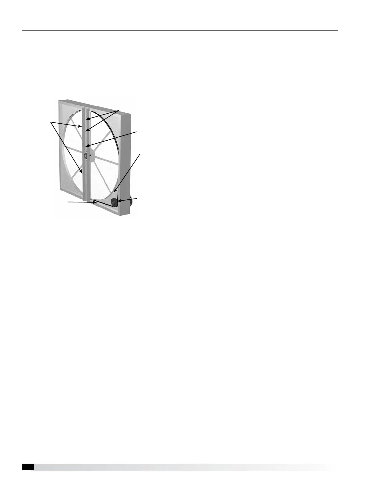
Drive Belt
Inspect the drive belt. Make sure the belt rides smoothly
in the pulley and around the outside of the wheel. Note
the directional arrow and data information shown in the
image.
Adjust the Air Seals
Make sure the unit power supply is locked out.
Disconnect the wiring to the wheel module and pull
the wheel cassette out of the cabinet on its tracks.
Large cassettes are not removable. Then slowly rotate
the wheel by hand to make sure there is no binding or
misalignment.
There is a perimeter seal located around the outside of
the wheel and a diameter seal across the face of the
wheel on both sides. Check to make sure that all air
seals are secure and in good condition.
Adjust the air seals by loosening all the air seal retaining
screws on the bearing support. Using a piece of paper
as a feeler gauge, adjust the seals so they almost touch
the face of the wheel while tugging slightly on the paper.
When the wheel is rotated, there should be a slight tug
on the paper. Tighten the screws, repeat the steps on
the other set of seals.
Push the wheel cassette back into the unit and plug
in the power connector. Turn the main power supply
back on and then observe the operation of the wheel by
opening the wheel access door slightly. Remove filters if
necessary to observe the wheel.
Drive Belt
Adjustable
Air Seals
Label
showing
cassette
serial # and
date code
Bearing
Support
Drive Pulley
Retaining
Screws