Dedicated Outdoor Air Unit 21
1. Compressor
2. High Limit Pressure Switch
The switch opens when refrigerant pressure
increases above the set point in the discharge line.
A manual reset is then required.
3. Hot Gas Reheat Valve (optional)
Units equipped with a reheat coil use a three-
way valve with actuator to control the supply
air discharge temperature of the unit during
dehumidification mode. The unit controller provides
a 0-10 VDC signal to control the amount of reheat
to meet the supply temperature set point
4. Hot Gas Reheat Coil (Optional)
5. Hot Gas Reheat Check Valve (Optional)
6. Outdoor Fans
7. Outdoor Coil
8. Refrigeration Accumulator
9. Liquid Line Filter Drier
10. Sight Glass
11. Four Way Reversing Valve
Each compressor circuit is equipped with a
reversing valve to reverse the direction of refrigerant
flow, switching the unit between heating and
cooling mode.
12. Electronic Expansion Valve (EXV) or
Thermostatic Expansion Valve (TXV)
An expansion valve is provided on each refrigerant
circuit. This valve controls the flow of liquid
refrigerant entering the indoor and outdoor coils
by maintaining a constant superheat. The TXV is
adjustable. Both the EXV and TXV are located on
the side of the outdoor coil and can be accessed
through the refrigeration system access panel.
13. Indoor Coil
14. Low Limit Pressure Switch
The switch is installed on the suction line and
disables the DX system when the suction pressure
drops below the set point. The switch will auto reset
when the pressure rises above the auto-reset set
point.
15. Service Access Ports
Typical port locations are shown. Additional valves
may be present in the system.
16. Refrigerant Pressure Transducers
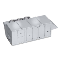
Factory-Installed Refrigeration System Components