Dedicated Outdoor Air Unit28
Start-Up Components
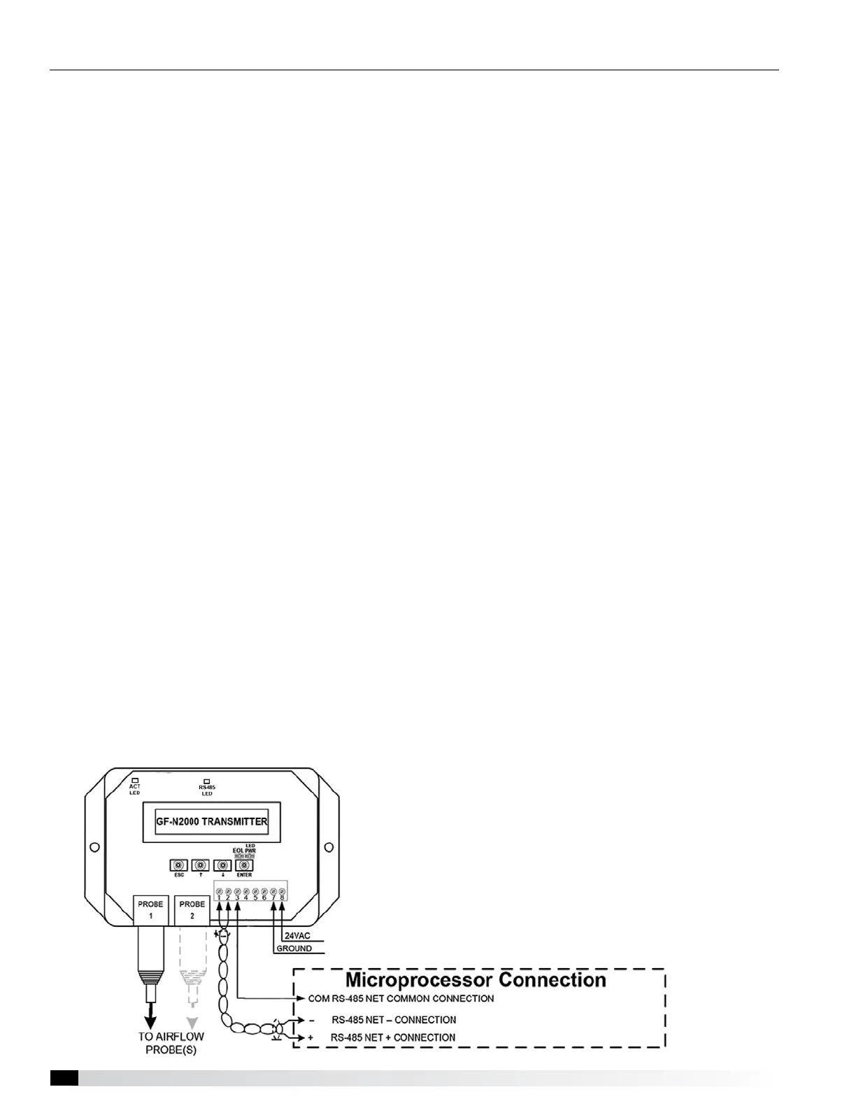
Airflow Monitoring
For additional information on how to navigate through
the airflow controller menus, refer to technical manuals
from GreenTrol® Automation Inc. at www.greentrol.
com. Also refer to the Greenheck Reference Guide for
Microprocessor Controller.
Display and Navigation
The LCD screen will by default show the current airflow
that is being measured. To enter the menu to set up the
monitoring station the user must remove the front cover
of the GreenTrol to uncover the navigation buttons.
Press and hold the UP and DOWN keys at the same
time for 3 seconds to enter the menu.
Enter Button Function - The ENTER button allows the
user to go into the selected menu or function, as well as
save the selected value.
Up/Down Button Function - The UP/DOWN buttons
are used to navigate the menu and to change values in
the menu.
Esc Button Function - The ESC button allows the user
to exit the current menu or function.
Field Calibration
1. Press UP/DOWN = Setup
2. Press DOWN/ENTER = Setup Wizard
3. Scroll Down to Field Adjust and press ENTER
4. Run FAK wizard and press ENTER
5. Set FAW Int and press ENTER
6. FAW INT = 300 and press ENTER
7. Set number of flows and press ENTER
8. Set flow and press ENTER
9. Set flow to actual CFM measured by Test and
Balance and press ENTER
10. Wait for calibration before cycling power
11. Proceed to Communication Setup
Communication Setup
1. Press the UP and DOWN keys at the same time for
3 seconds
2. When SETUP appears on the screen press ENTER
3. Scroll DOWN (twice) to the NETWORK menu and
press ENTER
4. When NETOUT appears on the screen, press
ENTER; when SET NETOUT appears on the screen,
press ENTER again
5. Scroll UP or DOWN to set the NETOUT = MODBUS
and then press ENTER
6. Scroll DOWN to NETADDR and press ENTER,
when SET NETADDR appears on the screen press
ENTER again
7. Scroll UP or DOWN to set the NETADDR to the
same address that was listed for the airflow monitor
in the microprocessor. For instance, the Outdoor
Airflow Monitor screen above has an address of 31.
Then press ENTER.
8. Scroll DOWN to NETBAUD and press ENTER,
when SET NETBAUD appears on the screen, press
ENTER again
9. Scroll UP or DOWN until NETBAUD = 19200, then
press ENTER
10. Scroll down to PARITY and press ENTER, when
SET PARITY appears on the screen press ENTER
again
11. Scroll UP or DOWN until PARITY = NONE2, then
press ENTER
12. Once the address is set and the communication
wires are connected, “Status” LED should be a
steady green and the “RS485” LED should be a
quick blinking green LED.