Label Description
E OSDP/Controller network (Max. 4 OSDP readers
F Ehternet switch RJ45. NOTE: All IP devices must have a valid IP address.
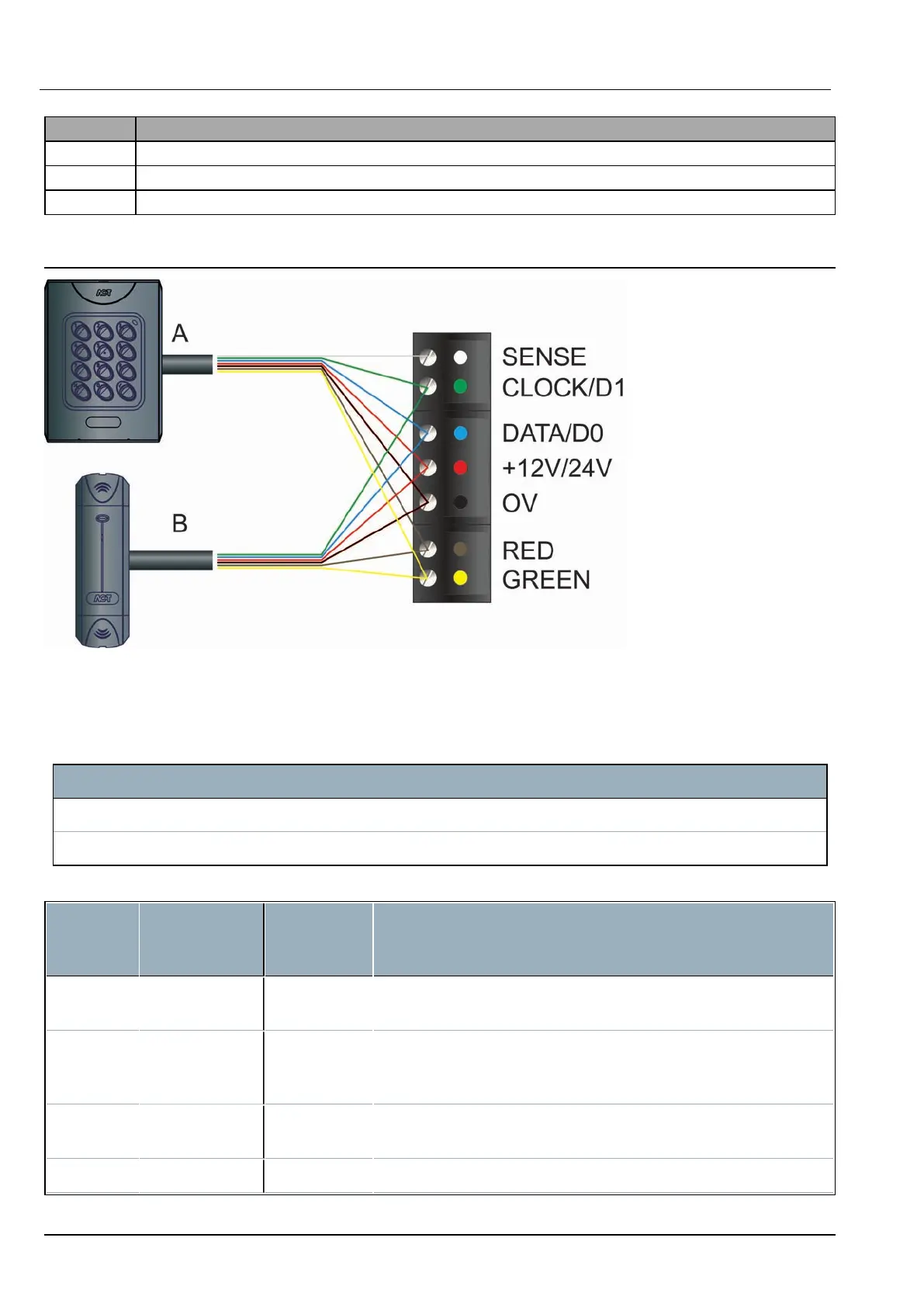
G Vanderbilt reader wire colour coding (Wiegand / Clock&Data interface).
3.2 Wiring Clock&Data entry and exit readers
For Clock&Data readers, wire exit readers in parallel with entry readers, but leave the sense line
unconnected for exit readers.
Max length: 100m with 12V DC
Cable: 8 core screened Belden 9504 (24 AWG) or equivalent.
Label Description
A Entry reader. ACTpro-1050 PIN and Proximity reader (EM1050, MF1050, EV1050).
B Exit Reader. ACTpro-1030 Proximity reader (EM1030, MF1030, EV1030).
3.2.0.1 Terminal block wiring
Reader
Terminal
Block
Recommended
Wiring colour
Controller
Input PIN
Signal Information
SENSE White SENSE For Entry readers connect the reader SENSE cable or terminal to
the SENSE input pin. For Exit readers, do not use this input.
CLOCK/D1 Green CLOCK/D1 This is the clock or strobe signal input on the ACTpro controller or
door stations. Connect the reader CLOCK/D1 cable or terminal on
the reader to CLOCK/D1 input pin.
DATA/D0 Blue DATA/D0 This is the Data input. Connect the reader DATA/D0 cable or
terminal on the reader to DATA/D0 input pin.
+12V/24V Red +12V/24V Positive +12V DC Supply voltage for the reader.
ACTpro-1500 Door Controller – Installation and Operating Instructions Wiring
© Vanderbilt 2020 8 A-100667
18.06.2020