WRM-10P/WRM-40 OPERATING INSTRUCTIONS
Table 2.0 Functional Descriptions of WRM-10P Controls and Indicators
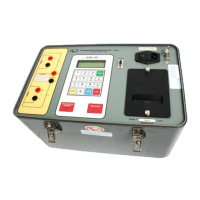
Fig. 1
Index
Panel Markings
Functional Descriptions
1
V1
Voltage sensing input channel #1. Female test
connector jacks for connecting voltage-sensing
test leads.
2
I
Current output. Female test connector jacks for
connecting current test leads.
3 (Not titled; LCD) Liquid-Crystal Display, 4-line by 20 character.
Back lighted and readable in sunlight. Displays
menus, user selections, status readouts and test
results.
4
RS-232C
Computer interface port, 9-pin connector; female
DB type. Data rate is set to 19,200 baud, 1 start
bit, 2 stop bits, 8 data bits and no parity bit.
PIN SIGNAL
2 Rx
3 Tx
5 Signal Gnd
5
120/240 2A, 50-60 Hz
Fuse: 250 Vac, 3A Slow
Blow
Input power connector with third-wire safety
ground, ON/OFF rocker toggle switch with
built-in fuse protection.
6
GROUND
5/16-18 threaded stud, with hand-turned wing
nut; Safety Ground; This must be connected to
station ground before connecting WRM-10P/40
test leads to the transformer.
7 (Not titled; thermal printer) Built in thermal printer; prints test results in the
field on 2.5-inch-wide paper. NOTE: For best
high-contrast print quality, it is recommended
that only VIC thermal paper be used.
8
DISCHARGE
Red LED indicator light. When lit, this indicator
warns the operator that the WRM-10P is
discharging the energy stored in the transformer.
). Do not disconnect test leads when this light is
on. Failure to heed this warning can result in
shock and/or fatal injury to personnel.
9 (Not titled; 16-key pad) Pushbutton operating controls; 10 key pad, plus
START, STOP, ENTER, CLEAR, two paper-
drive buttons. Number keys 2 thru 9 have dual
functions as letter entries (a la telephone dialer
key pad
 Loading...