31
32
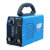
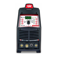
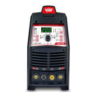
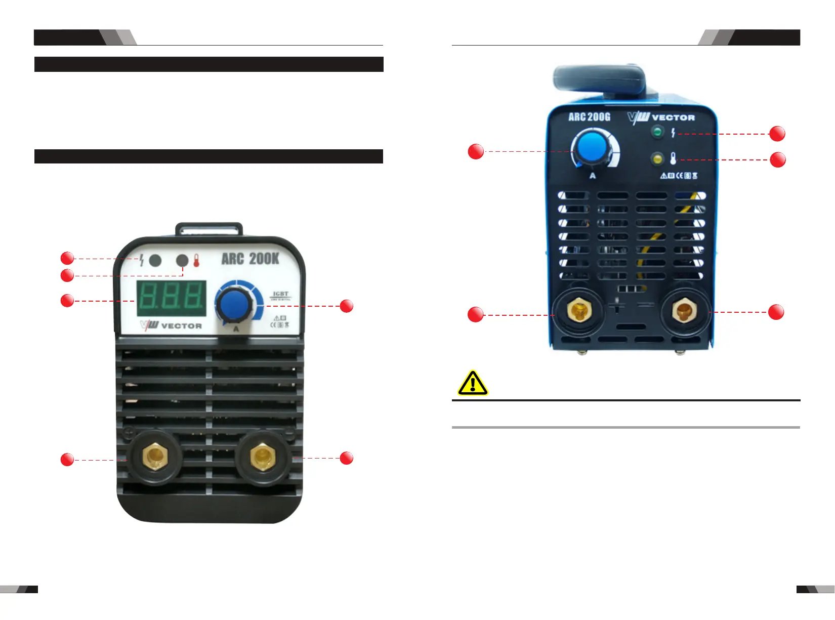
3.1 Layout for the panel
1. Power indicator
The green power indicator will be illuminated when the welder is turned ON and indicates
the presence of power.
DO NOT TOUCH the electrode wire while it is being fed through the system. The electrode
wire will be at welding voltage potential.
2.Thermal overload indicator light
This welding power source is protected by a self resetting thermostat. The indicator will
illuminate if the duty cycle of the power source has been exceeded. Should the thermal
overload indicator illuminate the output of the power source will be disabled. Once the
power source cools down this light will go OFF and the over temperature condition will
automatically reset. Note that the mains power switch should remain in the on position
such that the fan continues to operate thus allowing the unit to cool sufficiently. Do not
switch the unit off should a thermal overload condition be present.
WARNING
Operation
Operation
4
6
1
2
3
5
3. Digital Ammeter (ARC 200G Without this feature)
The digital Ammeter is used to display the actual output current of the power source.
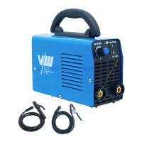
ARC SERIES EQUIPMENTARC SERIES EQUIPMENT
◆200 Amp electrode holder with 3M cable
◆300 Amp earth clamp with 3M cable
◆Operating Manual
2.6 Packaged items
4
1
2
5
6