1
2
3
4 5
6
7
88
53
54
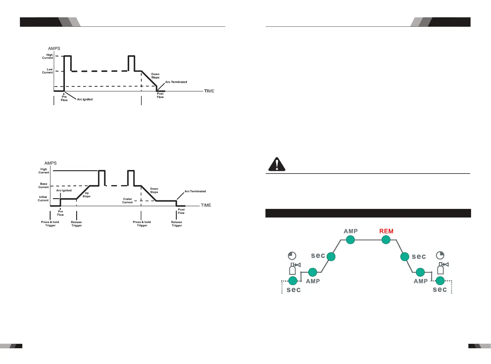
Minimum
Current
Press & hold
Trigger
Release
Trigger
Note: that when operating in GTAW (HF and LIFT TIG modes), the power source will
remain activated until the selected down slope time has elapsed
4T Latch mode this mode of welding is mainly used for long welding runs to reduce operator
fatigue. In this mode the operator can press and release the torch trigger and the output will
remain active. To deactivate the power source, the trigger switch must again be pressed
and released, thus eliminating the need for the operator to hold the torch trigger.
Operation
Operation
Press and hold the torch trigger to activate the power source (weld). Release the torch trigger
switch to cease welding.
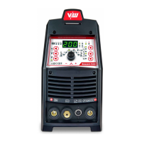
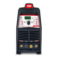
8. Prozess Knopf (WIG 200D No cutting function)
Die Prozess-Wahltaste dient zur Auswahl des gewünschten Schweißmodus. Es stehen
drei Modi zur Auswahl: GTAW (TIG), Manuelles Schweißen mit Stabelektrode (STICK)
und Schneiden (CUT).
9. Programming Parameter Indicators
These indicator lights will illuminate when programming.
10. Current adjusting button/functions choosing
Clockwise rotate to enlarge the current, and anti-clockwise rotate to reduce the current.
If you need to choose different programming parameters (the eighth mark), press the
button and release it to choose different functions.
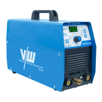
11. Positive Welding Terminal
Positive Welding Terminal. Welding current flows from the Power Source via heavy
duty bayonet type terminals. It is essential, however, that the male plug is inserted
and turned securely to achieve a sound electrical connection.
Note: CT 520PD positive pole press icon Connect the ground clip to the corresponding
function.
12. Negative Welding Terminal
Negative Welding Terminal. Welding current flows from the Power Source via heavy
duty bayonet type terminals. It is essential, however, that the male plug is inserted
and turned securely to achieve a sound electrical connection.
13. 5 Pin Control Socket
The 5 pin receptacle is used to connect a trigger switch or remote control to the welding
Power Source circuitry:
To make connections, align keyway, insert plug, and rotate threaded collar fully clockwise.
14. Gas output interface
The gas output interface on the front panel is a fast connection of a suitable TIG torch.
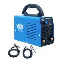
15. Power switch
before using the machine. Pull the switch to the closure state of “AN” to operate the
machine, and pull the switch to “AUS” after use. Turn off the power input, and the machine
will stop operating.
16. Gas input interface
The gas port is connected with the gas valve output port. After connection, check whether
there is gas leakage.
CAUTION
Loose welding terminal connections can cause overheating and result in the male plug
being fused in the terminal.
3.2 Control panel
.Gas Pre-Flow 1
WIG 200D / CT 520PD: Absolute setting range 0.1s to 5s (0.1S increments)
This parameter operates in TIG modes only and is used to provide gas to the weld zone
prior to striking the arc, once the torch trigger switch has been pressed. This control is
used to dramatically reduce weld porosity at the start of a weld.
DC TIG SERIES EQUIPMENTDC TIG SERIES EQUIPMENT