4.3 The explanation of welding quality
The relation of welding area color & protect effect of stainless steel
Protect effect
best better
good
bad
worst
Welding area color argent,golden
blue
red-grey
grey
black
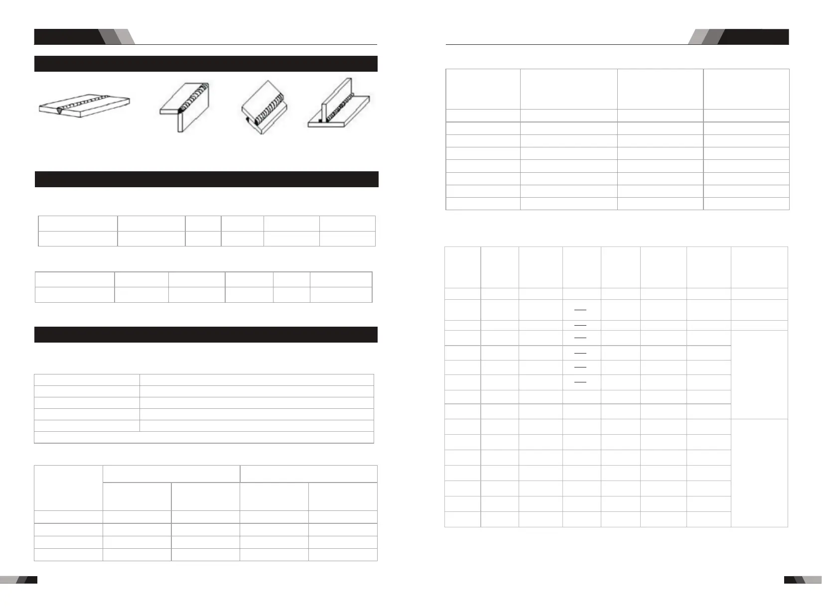
a butt joint b lap joint c coner joint d T joint
4.2 Joint froms in TIG
4.4 TIG parameters matching
The corresponding relationship between gas nozzle
diameter and electrode diameter
Gas nozzle diameter/mm
6.4
8
9.5
11.1
Electrode diameter/mm
0.5
1.0
1.6 or 2.4
3.2
Notice: the above parameters originate from <<Welding Dictionary>> P142,Volume 1 of Edition 2.
04
Gas nozzle and the shield gas flow rate
Welding
current range/A
DC positive connection
AC
Gas nozzle
diameter/mm
Gas flow
1
rate/L•min-
Gas nozzle
diameter/mm
Gas flow
1
rate/L•min-
10~100
101~150
151~200
201~300
4~9.5
4~9.5
6~13
8~13
4~5
4~7
6~8
8~9
8~9.5
9.5~11
11~13
13~16
6~8
7~10
7~10
8~15
Notice: the above parameters originate from <<Welding Dictionary>> P149,Volume 1 of Edition 2.
Protect effect
best better
good
bad
worst
Welding area color bright argent orange-yellow
blue-purple
caesious
white powder
of titanium oxid
The relation of welding area color & protect effect of Ti-alloy
Tungsten
Electrode
Diameter/mm
Sharpened of
the Electrode
Diameter/mm
Angle of Cone(º)
Background
Current/a
1.0
1.0
1.6
1.6
2.4
2.4
3.2
4.0
0.125
0.25
0.5
0.8
0.8
1.1
1.1
1.5
12
20
25
30
35
45
60
90
2~15
5~30
8~50
10~70
12~90
15~150
20~200
20~300
Tungsten Electrode
Welding techniqueWelding technique
63
64
Notice: the above parameters originate from《Welding Dictionary》P538,
Volume 2 of Edition 2.
Parameters of AC TIG(MMA) for Aluinum and its alloy
Steet
thickness
/mm
Welding
wire
diameter
/mm
Tungsten
eletrode
diameter
/mm
Pre-heat
Temper
-ature/ºC
Welding
current/A
Argon flow
1
rate/L•min-
Gas nozzle
diameter
/mm
Remark
1.6
1.6~2.0
2~2.5
2~3
3
3~4
4
4~5
4~5
2
2
2~3
3
4
4
5
5
5
100
100~150
45~60
50~80
90~120
150~180
180~200
180~240
240~280
260~320
280~340
1
1.5
2
3
4
5
6
8
10
7~9
7~9
8~12
8~12
10~15
10~15
16~20
16~20
16~20
8
8
8~12
8~12
8~12
10~12
14~16
14~16
14~16
Flange welding
Flange or butt
welding by
one side
Butt welding
V-groove
butt welding
12
14
16
18
20
16~20
22~25
4~5
5~6
5~6
5~6
5~6
5~6
5~6
5~6
5~6
6
6
6
6
6~7
150~200
180~200
200~220
200~240
200~260
200~260
200~260
300~360
340~380
340~380
360~400
360~400
300~380
360~400
18~22
20~24
20~24
25~30
25~30
25~30
30~35
16~20
16~20
16~20
16~20
20~22
16~20
20~22
X-groove
butt welding
DC TIG SERIES EQUIPMENTDC TIG SERIES EQUIPMENT