55
56
Operation
Operation
2.Initial Current
WIG 200D / CT 520PD: The main current Setting range 10AMP to 200AMP
This parameter operates in TIG modes and is used to set the starting current of TIG. The Start
Current remains on until the torch trigger switch is released after it has been depressed. (Can
be set in 2T or 4T mode.)
Note: The maximum initial current available will be limited to the set value of the base.
3.Up Slope
WIG 200D / CT 520PD: Setting ranges :0.1S-10S (0.1S increments)
This parameter operates in TIG modes only and is used to set the time for the weld current
to ramp up, after the torch trigger switch has been pressed then released, from Initial Current
to High or base current. (Can be set in 2T or 4T mode.)
4.Peak Current
WIG 200D / CT 520PD: Setting ranges
10AMP to 200AMP (DC TIG mode), 10 to 170A (STICK mode)
This parameter sets the TIG weld current. This parameter also sets the STICK weld
current.
6.Down Slope
WIG 200D / CT 520PD: Setting ranges 0.1-10s
This parameter operates in TIG modes only and is used to set the time for the weld current
to ramp down, after the torch trigger switch has been pressed to end current. This control
is used to eliminate the crater that can form at the completion of a weld.
5. Remote Control
The system independently identifies the remote control, and when the indicator light is
on, the welding current can be adjusted by remote (foot or welding gun).
7.End current
WIG 200D / CT 520PD: Setting ranges 10A-200A
This parameter operates in TIG modes only and is used to set the finish current for TIG. The
end Current remains ON until the torch trigger switch is released after it has been depressed.
(Can be set in 2T or 4T mode.)
Note: The maximum crater current available will be limited to the set value of the base
current.
8.Post Flow
WIG 200D / CT 520PD: Setting ranges 1-10S
This parameter operates in TIG modes only and is used to adjust the post gas flow time
once the arc has extinguished. This control is used to dramatically reduce oxidation of
the tungsten electrode.
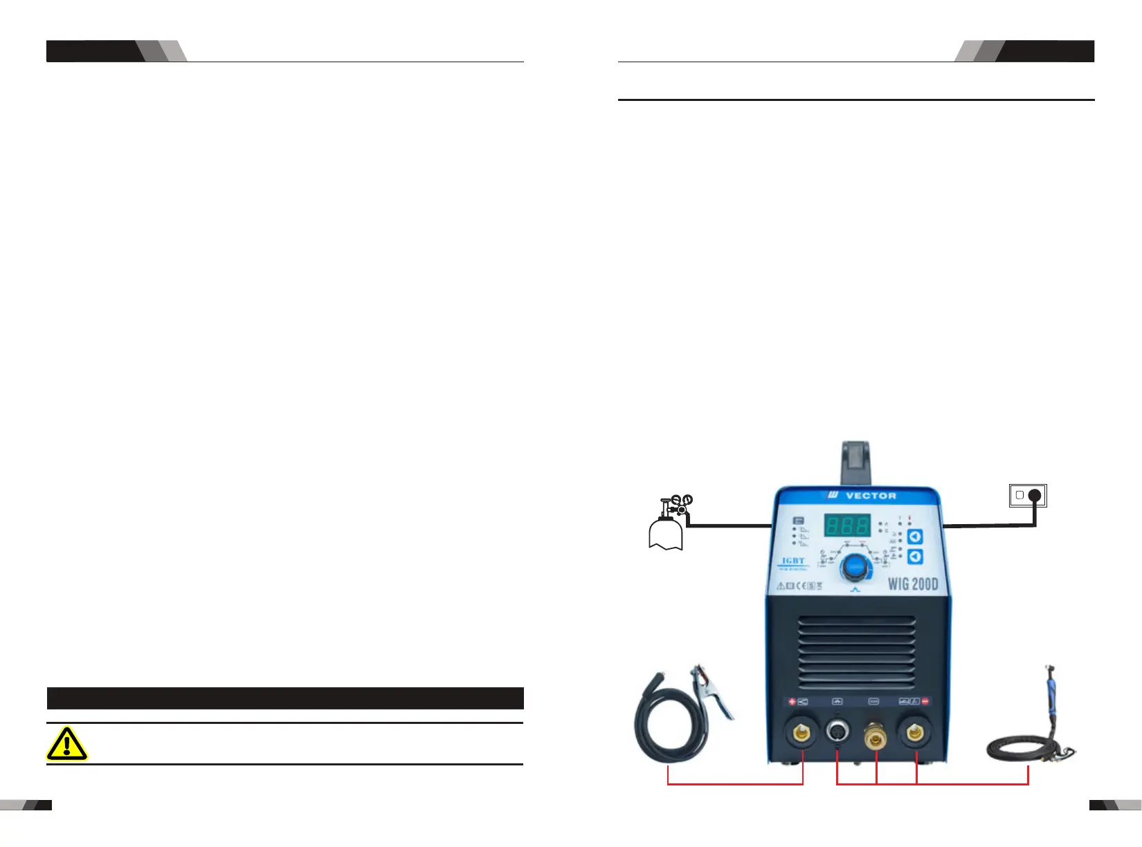
3.3 Set-up for LIFT TIG (GTAW) welding
WARNING
Before any welding is to begin, be sure to wear all
appropriate and recommended safety equipment.
NOTE
The following set up is known as Straight Polarity or DC electrode positive. This is commonly
used for DC LIFT TIG welding on most materials such as steel and stainless steel.
1. Switch the ON/OFF Switch (located on the rear panel) to OFF.
2. Connect the work lead cable to the positive output terminal, and the LIFT TIG Torch cable
to the negative output terminal.
3. Connect the gas line/hose to the proper shielding gas source.
4. Slowly open the Argon Cylinder Valve to the fully open position.
5. Connect the work lead clamp to your work piece.
6. The tungsten must be ground to a blunt point (similar to a pencil) in order to achieve optimum
welding results. See illustration. It is critical to grind the tungsten electrode in the direction
the grinding wheel is turning. Grind at a 30 degree angle and never to a sharp point.
7. Install the tungsten with approximately 1.6mm to 3.2mm sticking out from the gas cup,
ensuring you have correct sized collet.
8. Tighten the back cap.
9. Turn the switch to the “ON” position. The power L.E.D. light should illuminate.
10. Set the welding process to LIFT TIG.
11. Set the Weld Current Control Knob to the desired amperage.
12. You are now ready to begin LIFT TIG Welding.
Arg./Gas (TIG/WIG)
power supply
Earth Clamp
TIG Torch
DC TIG SERIES EQUIPMENTDC TIG SERIES EQUIPMENT