Magnetic Force Microscopy
15-308 Dimension 3100 Manual Rev. C
15.5 Installation of Extender Electronics Module
In Spring of 1994, Digital Instruments Veeco began making available its
Extender Electronics Module (sometimes referred to as “phase box” or “phase
extender”) for customers wanting phase detection and frequency modulation
MFM. For Dimension systems, the Extender is installed using 37-to-37 pin
ribbon cables between: 1) the NanoScope III or IIIA SPM controller and the
Extender Electronics Module; as well as 2) from the FM / Extender to the
microscope. A hardware change is also required; the main electronics
backplane board at the rear of the microscope must be swapped out (this may
be done by either the customer or a factory representative). Detailed
installation instructions are provided in Digital Instruments Veeco Support
Note No. 205. For more information, contact Digital Instruments Veeco.
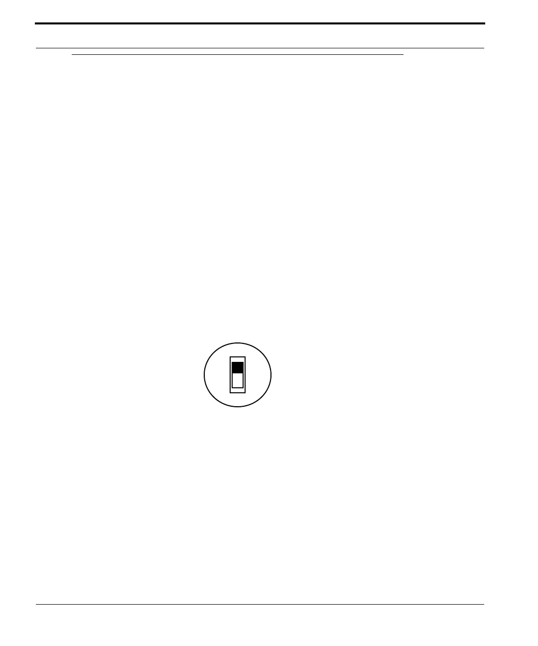
Note: The phase box is equipped with a slider
switch for switching internal electronics
between Dimension-series and MultiMode
SPM signals. This switch may be accessed
through a hole on the underside of the box as
shown below:
Figure 15.5a Phase Box
For Dimension-series SPMs, always set the switch to Dimension. Use a pencil
to access the switch through the hole.
Dimension
MultiMode
 Loading...