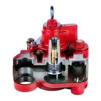
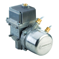
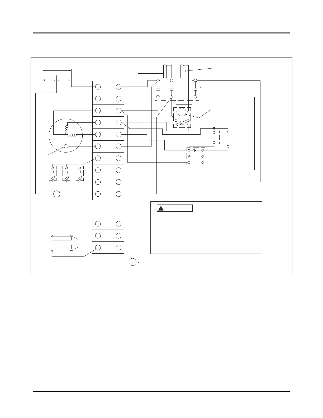
Installation Wiring the Conduit Box
12
Figure 4. Typical Mechanical Dispenser Motor Control Box, Wiring Diagram, 2HP
BLUE
1
Line
1
230V
115
Line
2
Orange
Orange
Orange
White
Starting relay
Starting
capacitor
Running
capacitor
Overload relay
reset button
Contactor
Contactor coil
terminals
1
5
2
T3
L3
L2
L1
T1 T2
White
White
White
Red
Red
Red
Black
Red
Red
Blue
Blue
Blue
Blue
Blue
Blue
Red
Red
Red
Motor
Blue
1
2
3
Ext
pilot
Three wire control
Ground screw
Two wire control
115V External
pilot light
(50W max.)
Low liquid
protector
Stop
Start
2
3
115
Black
Black
Black
Black
Black
Black
Black
The control box must be grounded for personal
safety. Refer to the National Electrical Codes and
applicable local codes for proper grounding
procedures.
Approved component only - total system installed
shall comply with all local codes. Make Ground
Connection In Accordance With Local Codes.
WARNING
 Loading...