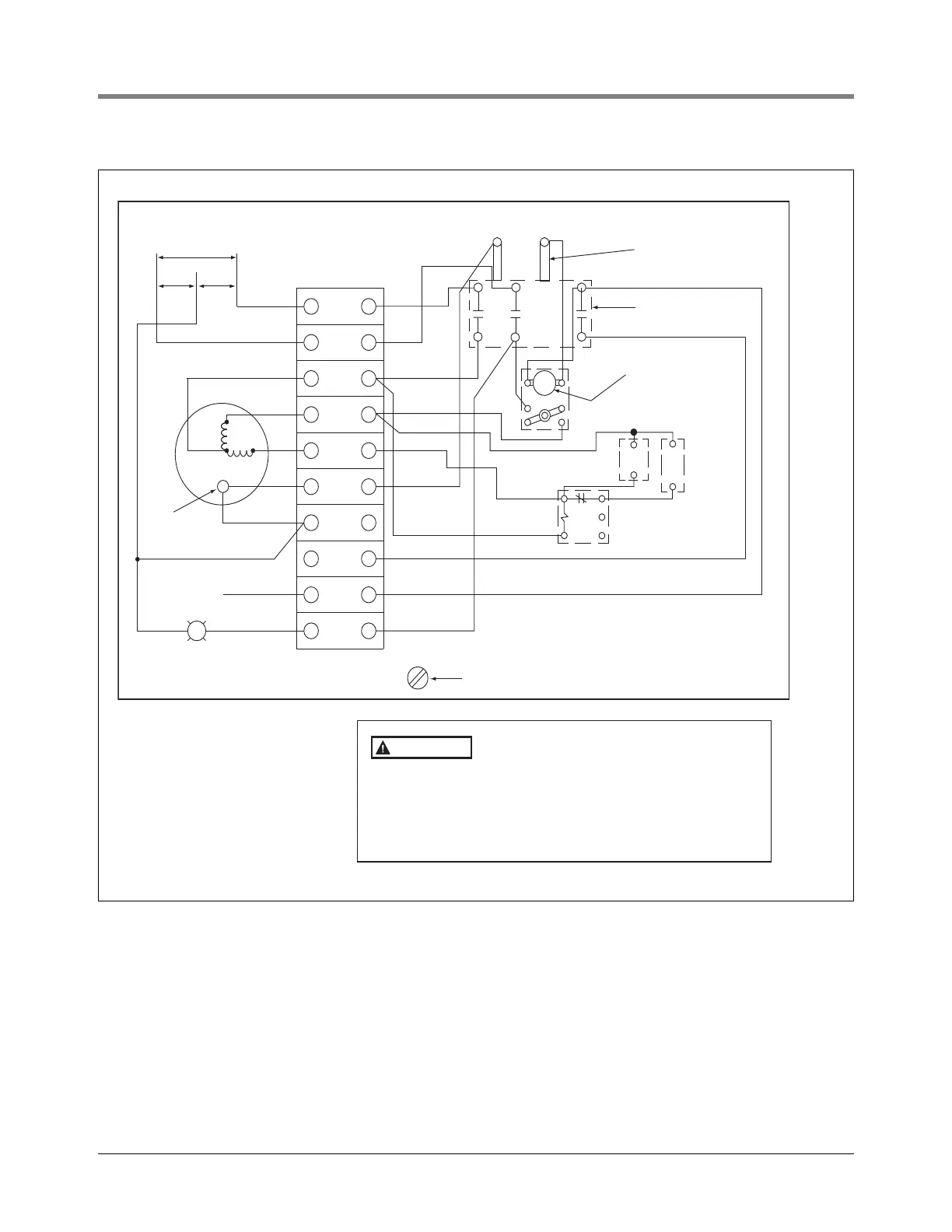
Figure 5. Representative Wiring Diagram For Use With Switched “Hot” Feed 208-230 Vac, 2HP Single-Phase Control Box
Line
1
230V
115
Line
2
Orange
Orange
Black
White
White
White
Starting relay
Starting
capacitor
Running
capacitor
Overload relay
reset button
Contactor
Contactor coil
terminals
1
5
2
T3
L3
L2
L1
T1 T2
White
Orange
Red
Red
Red
Black
115V
Coil
Red
Black
Black
Black
Blue
Blue
Black
Black
Red
Red
Blue
Blue
Motor
Blue
Blue
1
2
3
Ext
pilot
Ground screw
Hot
115V External
pilot light
(50W max.)
Low liquid
protector
115
rj/051-301-5 eps
208-230, 2HP 1Ø CONTROL BOX
1. Remove red wire (coil to L2).
2. Relocate orange wire at L1 to coil.
3. Change to 115V coil assembly.
The control box must be grounded for personal
safety. Refer to the National Electrical Codes and
applicable local codes for proper grounding
procedures.
Approved component only - total system installed
shall comply with all local codes. Make Ground
Connection In Accordance With Local Codes.
WARNING
 Loading...