Installation Installing Two Pumps for Tandem Operation
24
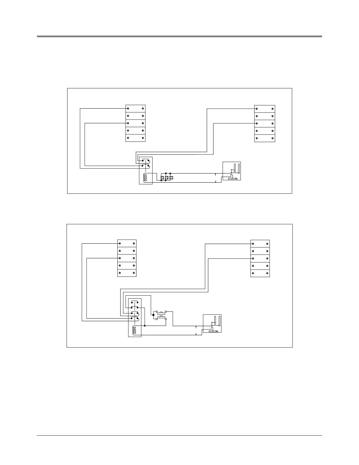
It is preferable that the wiring allow both submersibles to operate simultaneously with any combination of
dispensers turned on. To operate individually, the appropriate disconnect switch must be turned off manually. (See
Figure 13 through Figure 16 for suggested wiring diagrams.)
Figure 13. Suggested Diagram For Wiring Dual Manifold System, Two-Wire Control, 208/230 Single Phase
Figure 14. Suggested Diagram For Wiring Dual Manifold System, Three-Wire Control, 208/230 Single Phase
BL2
2
XPL
Dispenser Sw.
115V Relay
Allen Bradley
700C201
NEU
3
BL2
2
XPL
NEU
3
115V
PUMP 2PUMP 1
rj/051-301-15.eps
BL2
2
XPL
115V Relay
Allen Bradley
700C201
Switch at loading rack
NEU
3
BL2
XPL
NEU
3
2
115V
PUMP 1 PUMP 2
rj/051-301-16.eps
Start
Stop
 Loading...